Description of the pins
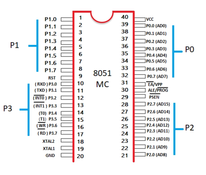
The 8051 microcontroller pin diagram is comprised of 40 pins, as may be seen below. Four Ports named P0, P1, P2, and P3 are used to store a total of 32 pins. Where each port has eight pins. The pin diagram and description for the microcontroller 8051 are therefore provided in this article.
Pins 1 to 8
It is also known as PORT 1. The 8-bit bidirectional input and output ports with inbuilt pull-up resistors make up PORT 1 Pins. Older 8051 microcontrollers only have an 8-bit I/O port on port 1. This port doesn't serve any additional purposes, unlike other ports.
Pin 9
It is an active HIGH pin, meaning the microcontroller will be reset if the RST Pin (Pin 9) is HIGH for at least two machine cycles. So it is the RESET pin used to reset it to its default values when operating or at the beginning of an application.
Pins 10 to 17
It is also known as PORT 3. Interrupts, timer input, control signals, serial communication signals Receive Data (RxD) and Transmit Data (TxD), and other operations are served by this port.
- Pin 3.0 - This pin is known as the serial input pin and its function is to receive data during serial communication.
- Pin 3.1 - This pin is known as the serial output pin and its function is to transmit data during serial communication.
- Pin 3.2 - This pin is used as an external trigger for interrupt 0.
- Pin 3.3 - This pin is used as an external trigger for interrupt 1.
- Pin 3.4 - This pin is for external input for Timer 0.
- Pin 3.5 - This pin is for external input for Timer 1.
- Pin 3.6 - This pin is used for writing data to the external memory.
- Pin 3.7 - This pin is used for reading data from the external memory.
Pins 18 and 19
The pins connecting an external oscillator are 18 and 19, or XTAL 2 and XTAL 1, respectively. A Quartz Crystal Oscillator is often attached here.
Pin 20
The ground pin on an 8051 microcontroller is pin 20, or GND. It connects to the power supply's negative terminal (0V), representing 0V.
Pins- 21-28
The PORT 2 Pins on the 8051 Microcontroller are Pins 21 through 28. The PORT 2 pins function as either inputs or outputs because it is a bidirectional port. Additionally, PORT 2 pins work as the higher-order address byte when external memory is interfaced.
Pin 29
Program Store Enable, often known as PSEN, is used to interpret signals from external program memory.
Pin 30
This pin is linked to Vcc(Voltage Common Collector) to drag it high if there is no requirement for external memory.
Pin 31
It is also known as Address Latch Enable or ALE and is used to demultiplex the port 0 address data indication (for external memory interfacing).
Pins 32 to 39
Pins 32 to 39 are known as Port 0 (P0.0 to P0.7), and they are multiplexed with low-order data/address bus signals to act as input/output ports (to provide the use of outer memory interfacing).
Pin 40 (VCC)
The circuit receives power supply voltage, or +5 Volts, from this pin, VCC (Voltage Common Collector).
The pin diagram of the 8051 microcontroller is as follows:
- VCC - This pin provides +5V power supply to the circuit.
- GND - This pin in connected to the negative terminal of the device to provide 0V supply.
- XTAL1 and XTAL2 - These pins are connected to the external oscillator to provide clock frequency.
- Reset - This pin is used to reset the microcontroller.
- Port 1 - This port is a collection of 8 bidirectional pins used for simple input/output operations. These do not serve any additional purpose.
- Port 2 - This port is a collection of 8 bidirectional pins used for simple input/output operations. These do not serve any additional purpose.
- Port 3 - This is a collection of 8 bidirectional pins.These act as higher-order address bytes whenever an additional external memory is interfaced with the 8051 microcontroller.
- Port 4 - This port is a collection of 8 bidirectional pins. These pins are used to provide functionality like Interrupts, Timer input, control signals and serial communication.
- INT0 - This pin is used as a trigger to external interrupt 0.
- INT1 - This pin is used as a trigger for external interrupt 1.
- T0 - This pin is used as external Timer 0.
- T1 - This pin is used as external Timer 1.
- WR - This pin gives the write signal for external memory.
- RD - This pin giver the read signal for external memory.
- ALE - This pin gives the signal to enable the latch to get the address for the external memory.
- PSEN - This pin is used to give the signal for accessing the program memory.
- 17-24. Address bus - These pins transmit address from the microcontroller to the external memory.
- 25-32. Data bus - These pins transmit data from the microcontroller to the internal memory.
- RST - This pins gives the signal that the microcontroller is being reset.
- EA - This pin is used for selecting the program memory.
- VPP - This pin is used in programming and configuration of the microcontroller.
- 36-39. XTAL - These pins are connected to the oscillator to provide clock frequency.
- P1.0 (AD0) – P1.7 (AD7) - These pins are used to interface external devices with the microcontroller.
Uses of pin diagram of the 8051 microcontroller
The pin diagram of 8051 serves many uses in embedded systems. Some of the main uses of pin diagram include:
- Pin identification - The pin diagram helps in identifying specific pins on the microcontroller. Each of these pins are labeled. This helps in easy identification of the pins.
- Hardware Connections - The pin diagram helps in making physical connections between the microcontroller and external devices. These devices may include sensors, displays, memory devices etc.
- Debugging and Troubleshooting - The pin diagram is useful for troubleshooting devices. With the help of pin diagram, we can compare the expected connections and signals on the pin diagram with the actual connections and identify the potential issues.
- Memory Expansion - The pin diagram helps in expanding the storage of a microcontroller. We can add additional memory to the microcontroller by interfacing external RAM and ROM to the microcontroller.
You can also read about mock interview.
Issues in Pin Diagram of the 8051 Microcontroller
The pin diagram of the 8051 microcontroller is standardized and well-defined. There are some issues associated with certain versions or derivatives of the 8051 microcontroller. There are several issues in the pin diagram of the 8051 microcontroller:
- Pin compatibility: Some of the microcontrollers may have additional pins or slightly different pin configurations. This can cause compatibility issues when using different versions from different manufacturers.
- Alternate pin functions: There are many cases where certain pins of the 8051 microcontroller can have multiple alternate functions. These functions can be interrupt inputs, UART pins, or timer/counter inputs. These alternate functions to specific pins may vary between different 8051 derivatives, leading to confusion during hardware design and programming.
- Incomplete or incorrect documentation: Documentation for some 8051 microcontrollers may be incomplete or contain errors regarding pin functions or electrical characteristics. This can create challenges for developers trying to use specific pins for custom applications.
- Pin voltage levels: The voltage levels supported by the I/O pins (high-level voltage and low-level voltage) can differ between various 8051 microcontrollers. This can impact the compatibility of the microcontroller with other components in a system.
- Pinout variations: Some 8051 derivatives come in different package types with varying pinouts. If you are working with different package versions of the same microcontroller, you need to be aware of the pinout variations to ensure proper connections and functionality.
Also read - AMD vs Intel
Frequently Asked Questions
How many pins are there in an 8051 microcontroller?
The 8051 microcontroller has a 40-pin dual in-line package (DIP). These pins are used for power supply, crystal oscillator, reset, input/output ports, serial communication, timers/counters, interrupt, and program memory. However, some variants of the 8051 may have different pin configurations.
Which pin of 8051 is used for Reset?
The Reset pin denoted as the “RST” or “RESET” an usually labelled as pin 9 is used to reset the microcontroller. When the RESET pin is high for at least two machine cycles the microcontroller is set the instruction to reset.
Which of the given pins of 8051 is activated?
The pins which are triggered in logic high state are called active high or activated pins. Some of the most common activated pins include the Port 0, Port 1, Port 2, Port 3, XTAL1, XTAL2 etc.
What are the input pins in 8051 microcontroller?
The 8051 microcontroller has four input pins. These pins are also known as port input pins or general-purpose I/O (GPIO) pins. These pins are programmable and can be configured to function as input or output pins based on the needs of the application.
What is the PIN number of ALE in 8051?
In the 8051 microcontroller, the ALE (Address Latch Enable) pin is designated as pin 30. ALE is used to latch the address onto external address latches during the address phase of a memory or I/O operation, ensuring proper data handling and memory access.
Conclusion
The 8051 microcontroller's pin diagram is fundamental for designing and implementing embedded systems. Each pin has a specific role, including power supply, I/O operations, timers, interrupts, and serial communication, which collectively enable the microcontroller to perform complex tasks efficiently. A clear understanding of the pin diagram ensures effective utilization of the 8051's capabilities, facilitating successful integration into various electronic projects and applications.
To better understand topics like the 8051 Microcontroller Pin Diagram, check the articles below.
Don't stop yourself here. Also, practice data structures and algorithms, interview questions, DBMS, computer networks, and operating systems to crack the interviews of big tech giants. Explore other fields like machine learning, deep learning, computer vision, and big data. Also, check out Interview Experiences for different companies.
Happy learning!


 9+ registered

