In computer architecture, address sequencing is the process of generating a sequence of memory addresses. It is a crucial method in computer architecture and with proper and efficient address sequencing, computers can access data quickly and effectively, making it a vital aspect of computing.
The microinstructions are stored in groups in the control memory. Each group is utilized to specify a routine in this case. Each computer's control memory contains instructions that contain their micro-programs routine. These micro-programs create the micro-operations employed to carry out the instructions.
Assume that the hardware is in charge of controlling memory address sequencing. In that instance, the hardware must be able to branch from one routine to the next and apply microinstruction sequencing within a routine.
Now Let’s understand how to transform the bits of instruction code into an address.
When attempting to execute a single instruction of the computer, the control must go through the following steps:
- The CAR (Control Address Register) must first be loaded with an initial address when a computer is turned on. The first microinstruction address can be described as this address. We can activate the instruction fetch routine with the help of this address.
- The control memory will then run through the routine utilized to determine the operand's effective address.
- The next step is to create a micro-operation that will execute the instruction fetched from memory.
With the help of control memory, where the routine is stored, we can convert the bits of instruction code into an address. This process is known as the Mapping Process. The control memory requires address sequencing capabilities, which are stated as follows:
- The address sequencing selects the conditional or unconditional branch based on the status bit conditions.
- Addressing sequence can increase the Control Address Register (CAR).
- It provides the facility for subroutine calls and returns.
- The addressing sequence provides a mapping from the bits of the instruction to a control memory address.
Recommended Topic, Microinstruction in Computer Architecture

Selection of Address for Control Memory
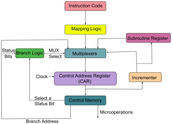
The diagram of a control memory and related hardware is shown above, which is required for selecting the address of the next microinstruction. In the control memory, the microinstruction is used to store a set of bits. We can start micro-operations in a computer register with the help of some bits. The remaining microinstruction bits are used to describe the technique for obtaining the following address.
In the above diagram, we can also observe that the control address register can retrieve its address using four distinct directions. With the help of the incrementer, the CAR is incremented, and then the next instruction is selected. The branching address will be determined in many microinstruction fields to produce branching results.
We can utilize conditional branching if there are status bits of microinstruction and if we want to apply conditions on them. A mapping logic circuit can be used to share an external address. A special register will save the return address. When the micro-program returns from the subroutine, this saved address will come in handy. It needs the value from the individual register at that point.
Read about Instruction Format in Computer Architecture Demultiplexer
Conditional Branching
In the above diagram, we can see, the branch logic is used to provide decision-making capabilities in the control unit. In the system, there exist special bits that are described by the status conditions. These bits provide parameter information such as mode bits, sign bits, carry-out, and input or output status.
When these status bits are combined with the microinstruction field, they can determine the outcome of a conditional branch formed by branch logic. The microinstruction field will define a branch address in this case. The branch logic hardware is implemented using the multiplexer. It will branch to the original address if the condition is met. Otherwise, the address register will be incremented.
The unconditional branch microinstruction can be implemented by loading the branch address into the control address register from control memory. If the condition is true, it will proceed to the branch, which is the address from the current microinstruction's next address field. Otherwise, it will collapse. The following conditions must be tested: Z(zero), C(carry), O(overflow), N(negative), and so on.
Recommended Topic - Shift Registers in Digital Electronics
Mapping of Instructions
If the microinstruction specifies a branch to the first work, a particular type of branch will be created in the control memory. Their micro-program routine is contained in this instruction. The status bits in this unique branch will be the bits in the operation code, which is a part of the instruction.

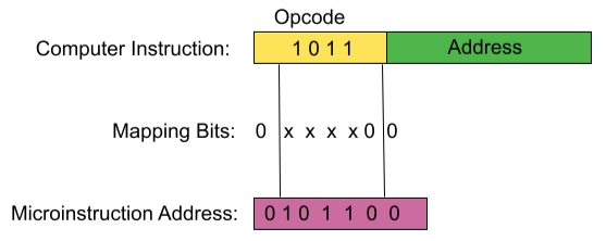
Mapping From Instruction code to Microinstruction address
The image above depicts a simple mapping mechanism that will turn a 4-bit operation code into a 7-bit address for control memory. The 0 will be inserted in the most significant bit of the address throughout the mapping process. The four operation code bits will be sent after that. Finally, the two least significant bits of CAR will be cleared.
Each computer instruction will receive a micro-program as a result of this process. Four microinstructions can be stored in the micro-program. The unused memory location can be used for other routines if the routine uses less than four microinstructions. If the routine uses more than four microinstructions, it will use the addresses 1000000 through 1111111.
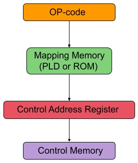
With the help of a PLD (programmable logic device) or ROM (Read-only memory), this concept can be extended to a more generic mapping rule.

Mapping Function Implemented by PLD and ROM
The above image represents the mapping of a microinstruction's address to an instruction's OP-code. This microinstruction is the starting microinstruction in the executed program.


