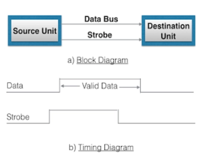
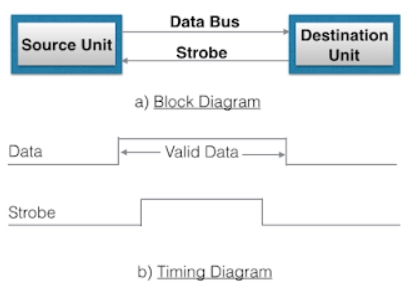
2. Handshaking method
The strobe control method for asynchronous data transfer has a disadvantage. The source unit always assumes that the destination unit has received the data placed in the data bus. Similarly, the destination unit that initiates the transfer takes that the source unit has placed data on the bus.
This problem is solved by the handshaking method of data transfer. In this method, we also have a second control line that provides the unit that initiates the transfer with a relay.
In the Handshaking method, one control line is in the direction of the bus's data flow, i.e., from source to destination. The source unit uses it to inform the destination unit if the data is valid in the bus. The second control line is in the opposite direction, i.e., from destination to source. The destination unit uses this control line to inform the source unit of accepting the data. And also, the sequence of control depends on the unit that first initiates the transfer.
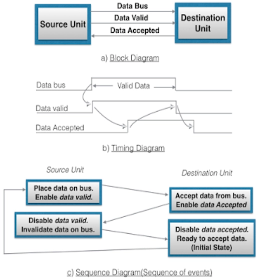
Source initiated handshaking: In the figure below, we can see that we have two handshaking lines, "data valid" and "data accepted," generated by the source unit and the destination unit, respectively.
Source: coagarage.blogspot.com
The timing diagram shows that the source initiates the transfer by placing the data on the data bus and enabling its data valid signal. The destination then activates a data accepted signal after it accepts the data from the bus. The source then disables the valid data signal, which makes the data on the bus invalid. Finally, the destination disables the data accepted signal, and hence the system goes into its initial state. We have a surety that the destination unit has read the data on the data bus through the accepted signal.
Destination initiated handshaking: In the figure below, we can see that we have two handshaking lines, "data valid" and "ready for data" generated by the source unit and the destination unit, respectively.
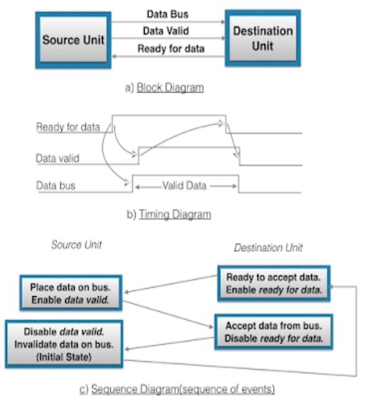
Source: coagarage.blogspot.com
In destination initiated, the destination unit initiates the transfer, so the source unit does not place data on the bus until it receives a ready-for-data signal from the destination. After that, the handshaking process is the same as the source initiated.
3. Asynchronous Serial Transfer
The data transfer between two units can be done in either series or parallel. In parallel data transfer, every message bit has its own direction, and the whole message is sent at a similar time. This defines that an n-bit message must be sent through n separate conductor paths.
In serial data transmission, every message bit is transmitted in sequence one by one at a time. This approach requires only one conductor or one conductor pair and common ground. The parallel transfer is quicker but requires multiple conductors. We use it for shorter distances and where speed is crucial. A serial transfer is easy and less costly as it requires only one conductor pair.
Serial transmission can be asynchronous or synchronous. In synchronous transmission, two units transfer common clock frequency, and data bits are sent frequently at the cost decided by the clock pulses. In asynchronous serial transmission, binary data is transmitted only when required, and the line waits idly if there is no data to be sent.
4. Asynchronous Communication Interface
An Asynchronous communication interface functions both as a receiver and a transmitter. The interface is boot up for any specific mode of transfer using the control byte that is loaded into the control register. The transmitter register receives a data bit from the CPU by the data bus. This data bit is sent to a shift register for serial transmission.
The receiver end receives serial information in a different shift register, and when a finalized data bit is acquired, it moves to the receiver register. The CPU may choose the receiver register to read the data bit through the data bus. The bits in the status register are utilized for output and input flags and for recording specific errors that can appear during the transmission.
Advantages of Asynchronous Data Transfer
- It is more flexible, and the devices can exchange data at their own pace.
- Each data character can finish by itself, guaranteeing that even if a packet is corrupted, its predecessors and successors will not be impacted.
- The receiving device does not need to perform any complicated tasks. Furthermore, since the device can keep up with the data stream, inconsistent data transfer does not cause a serious issue. Asynchronous transfers are now appropriate for situations where character data is produced erratically.
Disadvantages of Asynchronous Data Transfer
- These transmissions must recognise the start bits in order to be successful. Unfortunately, line interference can easily cause this, leading to the corruption or distortion of these bits.
- There is no useful information regarding the transferred data because a significant percentage of the transmitted data is used to control and identify header bits. Consequently, more data packets must always be supplied.
Frequently Asked Questions
What are the different ways for asynchronous data transfer?
Asynchronous data transfer between data can occur in two ways parallel and serial. In parallel, multiple control lines are used to send a single bit, whereas, in serial transfer, every bit is sent one at a time.
What is a asynchronous data transfer?
Transfer between the two units is referred to as synchronous if the registers in the I/O interface and CPU registers use the same clock. However, because internal timing in each unit is often independent of one another, each needs a separate clock for internal registers.
What is synchronous vs asynchronous data transfer?
The transmission time interval is constant in synchronous transmission. The period between transmissions in the asynchronous transmission is unpredictable and not continuous. Data is transmitted asynchronously in the form of bytes or characters. Half-duplex transmission is the type used in this.
What is a dma and dma controller?
Direct Memory Access (DMA) allows peripherals to transfer data directly to memory without CPU involvement. A DMA controller manages these transfers efficiently.
Is asynchronous online or offline?
Asynchronous communication can be both online and offline. Online examples include emails and messaging apps, while offline examples include scheduled batch processing.
Conclusion
We have extensively discussed asynchronous data transfer using different methods like strobe control method and handshaking methods. Asynchronous serial transfer and asynchronous communication interface were also discussed.
