CAN Physical Layers
The ISO/OSI Reference Model defines seven layers, beginning with the physical connection and progressing to the real user application, referred to as the Application Layer.
The conventional CAN Bus implementation ignores the link between the Data Link Layer and the Application Layer to preserve memory resources by reducing overhead and, consequently, enhancing performance as needed for embedded systems with limited resources.
After all, all levels above the Data Link Layer necessitate the use of additional software resources (higher layer protocols).
Most CAN physical layer methods involve twisted-pair copper wire with a common ground to enable physical transmission. Naturally, all linked nodes must support the same bit-rate(s) and bit-timing parameters.
The following physical medium attachment (PMA) options are available:
- CAN high-speed transceiver with low-power and selective wake-up capabilities (ISO 11898-2:2016)
- Transceiver with CAN SIC (signal enhancement capability) (CiA 601-4)
- Transceiver CAN XL SIC (CiA 610-3)
- Low-power, fault-tolerant CAN transceiver (ISO 11898-3:2006)
- CAN transceiver for trucks/trailers (ISO 11992-1)
- A single-wire CAN (SWC) transceiver (SAE J2411) is highly recommended for new designs.
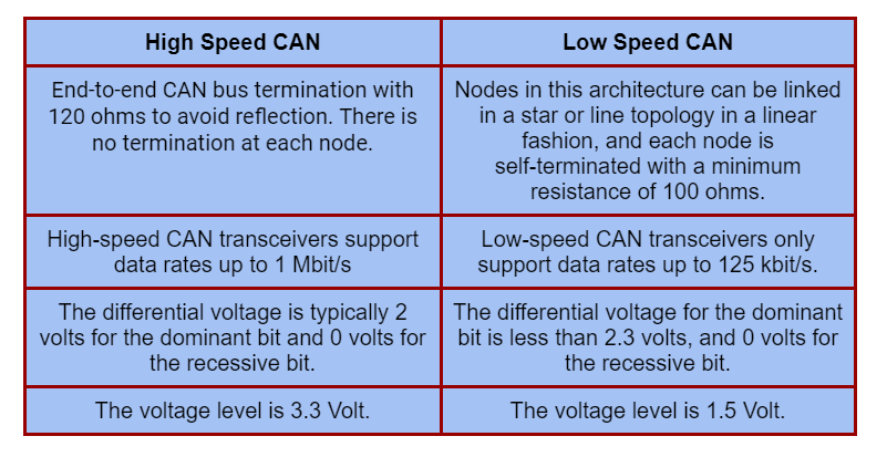
High Speed CAN vs Low Speed CAN
As per CAN standard, there are two types of CAN standards following at the physical layer:
Advantages of CAN
The CAN bus standard is widely utilized and is found in almost all cars and machinery. This is mostly due to the following significant advantages:
- Low Cost: CAN chipsets are widely accessible and reasonably priced.
- Fully centralized: the CAN bus offers a single point of contact for all network ECUs, allowing for central diagnostics, data logging, and setup.
- Extremely Durable: The system is resistant to electric disturbances and electromagnetic interference, making it perfect for safety-critical applications (e.g. vehicles)
- Efficient: CAN frames are prioritized by ID numbers. The highest priority data receives instant bus access without interfering with other frames.
- Reduced Vehicle Weight: by removing kilometers of strongly insulated electrical lines and their weight from the vehicle.
- Easy Deployment: It is a tried-and-true standard with a robust support environment.
Disadvantages of CAN
Following are some of the disadvantages of CAN Interface:
- The network's maximum number of nodes is not stated. Due to electrical overload, it can sustain up to 64 nodes.
- It has a maximum length of 40 meters.
- It is likely that there will be undesirable interactions between nodes.
- It incurs additional costs for software development and maintenance.
- A CAN driver must provide at least 1.5V over a standard 60 Ohm resistance.
- The network should be connected in a way that minimizes stubs as much as feasible.
- The CAN bus should be appropriately terminated with resistors at both ends to prevent signal integrity difficulties like reflections.
Importance in IoT
The EtherCAN (Ethernet to CAN gateway) bundle from Kvaser enables the application of Internet-of-Things (IoT) ideas by transferring data from any CAN Bus device or system via a corporate network or the Cloud using the Kvaser CANlib API. Users of the EtherCAN HS can also connect to the device via the built-in Rest API for web-enabled devices, such as smartphones.
The EtherCAN HS is ideal for sophisticated applications such as ECU reflashing since it is a programmable interface. For example, the software might interpret CAN Bus communications locally, that is, within the device, avoiding the need for WiFi or Ethernet delay.
FAQs
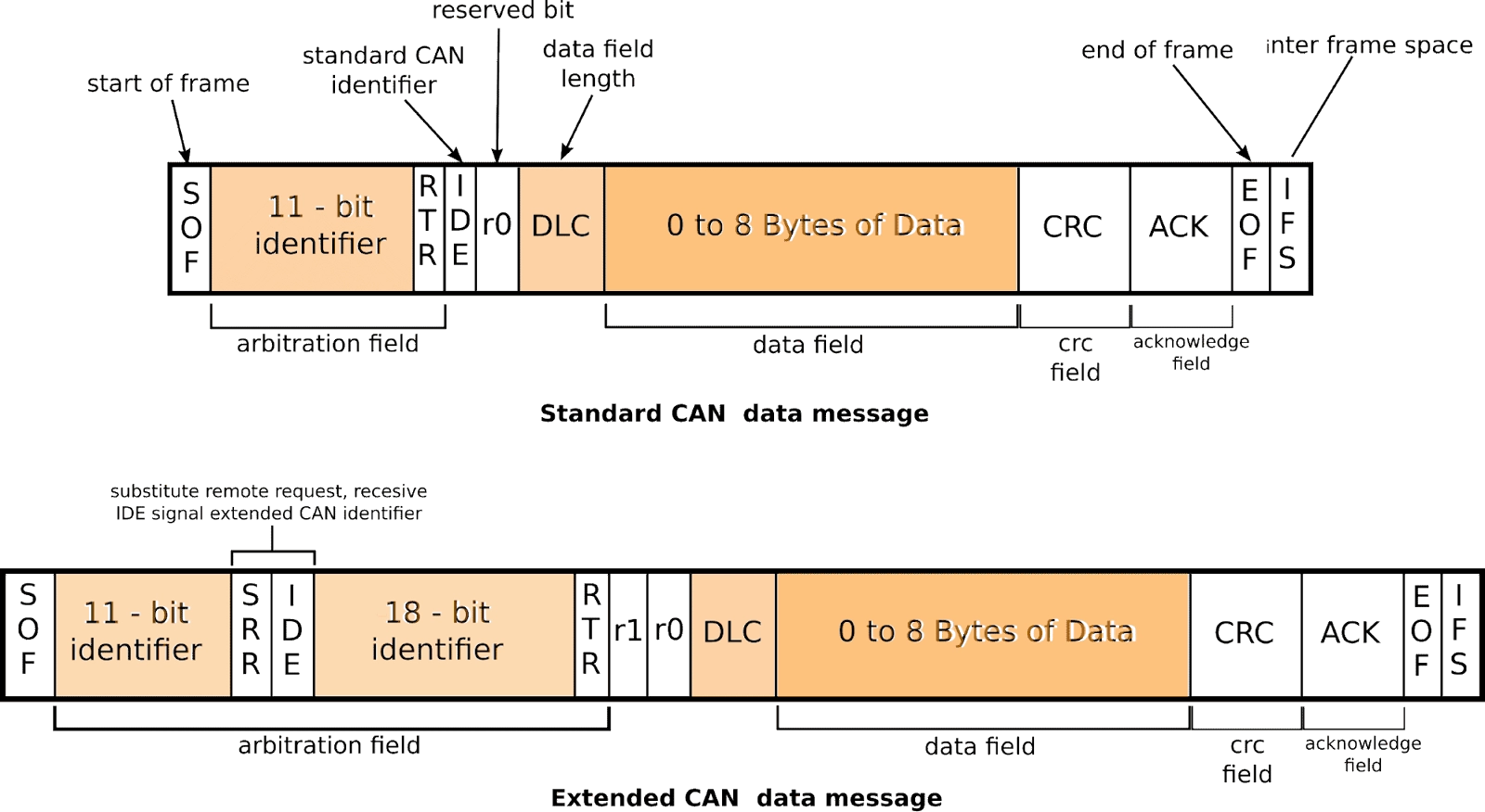
What are standard CAN Frame Formats?
The data frame is the only frame for actual data transmission. There are two types of messages:
- Base frame format: with 11 identifier bits
- Extended frame format: with 29 identifier bits
What are the features of the CAN protocol?
CAN protocol has only a few functionalities:
- Configuration is simple and flexible.
- CAN is a Message-Based Protocol.
- Message priority with identifier selection.
- Multi-master communication is possible.
- Fault Confinement and Error Detection are features.
- When the bus is idle, the corrupted message is immediately retransmitted.
What is the basic principle of CAN protocol?
CAN protocol is based on Wired AND logic. Wired AND logic indicates that 0 is dominant. Zero dominant means that anytime there is a disagreement between two data transmissions, the sender who is transmitting 0 gets priority.
Conclusion
In this blog, we have extensively discussed CAN Interface. We have also discussed the working of the CAN interface, its physical layers, and the difference b/w High Speed CAN and Low Speed CAN. Finally, we have concluded the blog with the advantages and disadvantages of CAN and its importance in IoT.
We hope that this blog has helped you enhance your knowledge regarding the topic of CAN interface, and if you would like to learn more, check out more stuff on our platform Coding Ninjas Studio.
Refer to our Guided Path on Coding Ninjas Studio to upskill yourself in Data Structures and Algorithms, Competitive Programming, JavaScript, System Design, and many more! If you want to test your competency in coding, you may check out the mock test series and participate in the contests hosted on Coding Ninjas Studio! But if you have just started your learning process and are looking for questions asked by tech giants like Amazon, Microsoft, Uber, etc; you must look at the problems, interview experiences, and interview bundle for placement preparations.
Nevertheless, you may consider our paid courses to give your career an edge over others!
Recommended Readings:
Bus and Memory Transfer
Do upvote our blogs if you find them helpful and engaging!
Happy Learning!


 9+ registered

