


Introduction
A combinational circuit is the digital logic circuit in which the output depends on a combination of inputs at that point of time with total disregard to the past state of the inputs. The digital logic gate is the building block of combinational circuits.
Question 1: In the following truth table, V = 1 if and only if the input is valid. What function does the truth table represent?
| Inputs | Outputs | |||||
| D0 | D1 | D2 | D3 | X0 | X1 | V |
| 0 | 0 | 0 | 0 | X | X | 0 |
| 1 | 0 | 0 | 0 | 0 | 0 | 1 |
| X | 1 | 0 | 0 | 0 | 1 | 1 |
| X | X | 1 | 0 | 1 | 0 | 1 |
| X | X | X | 1 | 1 | 1 | 1 |
- Priority Encoder
- Decoder
- Multiplexer
- Demultiplexer
Solution: (A) Priority Encoder
Explanation:
When the input is valid, it is a Priority encoder V=1 since there is more than one output and the number of outcomes is smaller than the number of inputs. For a priority encoder, it verifies the first high bit encountered. Except that all have at least one bit high, and 'x' stands for "don't care" because we've already identified a high bit.
So that's the answer (A).
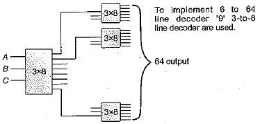
Question 2: How many 3-to-8 line decoders with an enable input are needed to construct a 6-to-64 line decoder without using any other logic gates?
- 7
- 8
- 9
- 10
Solution: (C ) 9
Explanation
Question 3: In a look-ahead carry generator, the carry generate function 𝐺𝑖 and the carry propagate function 𝑃𝑖 for inputs 𝐴𝑖 and 𝐵𝑖 are given by:
𝑃𝑖=𝐴𝑖⊕𝐵𝑖 and 𝐺𝑖=𝐴𝑖𝐵𝑖
The expressions for the sum bit 𝑆𝑖 and the carry bit 𝐶𝑖+1 of the look ahead carry adder are given by:
𝑆𝑖=𝑃𝑖⊕𝐶𝑖 and 𝐶𝑖+1=𝐺𝑖+𝑃𝑖𝐶𝑖, where 𝐶0 is the input carry.
Consider a two-level logic implementation of the look-ahead carry generator. Assume that all 𝑃𝑖 and 𝐺𝑖 are available for the carry generator circuit and that the AND and OR gates can have any number of inputs. The number of AND gates and OR gates needed to implement the look-ahead carry generator for a 4-bit adder with 𝑆3,𝑆2,𝑆1,𝑆0 and 𝐶4 as its outputs are respectively:
- 6, 3
- 10, 4
- 6, 4
- 10, 5
Solution: (B) 10, 4
Explanation:
let the carry input be c0 Now,
c1 = g0 + p0c0 = 1 AND, 1 OR
c2 = g1 + p1g0 + p1p0c0
= 2 AND, 1 OR
c3 = g2 + p2g1 + p2p1go + p2p1p0c0
= 3 AND, 1 OR
c4 = g3 + p3g2 + p3p2g1 + p3p2p1g0 + p3p2p1p0c0
= 4 AND, 1 OR
As a result, the total number of gates is 1+2+3+4 = 10, and the total number of OR gates is 1+1+1+1 = 4.
Question 4: We consider the addition of two 2’s complement numbers bn-1bn-2…b0 and an-1an-2…a0. A binary adder for adding unsigned binary numbers is used to add the two numbers. The sum is denoted by cn-1cn-2…c0 and the carry-out by cout. Which one of the following options correctly identifies the overflow condition?
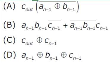
- A
- B
- C
- D
Solution: (B) B
Explanation
Overflow happens only when two binary values with the same sign are added, and the result is a different sign in the 2's complement form. Otherwise, there will be no overflow.
(A) 0111+0111=1110 has an overflow, yet the given condition is violated.
(C) Although there is no overflow in 1001+0001=1010, the provided condition is violated.
(D) There is no overflow in 1111+1111=1110; however, the specified condition is violated. Option (B) is the only one that is correct.
Question 5: Consider a multiplexer with X and Y as data inputs and Z as control input. Z = 0 selects input X, and Z = 1 selects input Y. What are the connections required to realize the 2-variable Boolean function f = T + R, without using any additional hardware ?
- R to X, 1 to Y, T to Z
- T to X, R to Y, T to Z
- T to X, R to Y, 0 to Z
- R to X, 0 to Y, T to Z
Solution: (A)- R to X, 1 to Y, T to Z
Explanation
For mux, we will have an equation like z'x+zy -----(1).
Now putting X=R, Y=1, and Z=T in eq(1), we find-
- T'R+T (1)
- T+T'R
- T+R (SINCE a+a’b=a+b)
So the answer is (A) part.
Question 6: A 4-bit carry look ahead adder, which adds two 4-bit numbers, is designed using AND, OR, NOT, NAND, NOR gates only. Assuming that all the inputs are available in both complemented and uncomplemented forms and the delay of each gate is one time unit, what is the overall propagation delay of the adder? Assume that the carry network has been implemented using two-level AND-OR logic.
- 4-time units
- 6-time units
- 10-time unit
- 12-time units
Solution: (A)- 4-time units
Explanation
Let C1 stand for the input carry to the first adder.
Now, to calculate C2, we require = P1C1 + G1 = 4 gate levels (P1 takes 2 gate levels), and to calculate S1, we need = P1 XOR C1 = 2 + 2 = 4 gate levels.
Because it is a Carry look-ahead adder, computing C3 does not require S2 to wait for the preceding adder's carry output C2, as C2, C3, and so on will all be computed at the same time.
S2 is now calculated as P2 XOR C2 = P2.C2' + P2'. C2 = P2 (P1.C1 + G1)' + P2' (P1.C1 + G1) [Note that the output carry from the first adder C2 is not used anywhere in this code] It can be implemented with the help of four gate levels The overall propagation delay is 4 gate level since the outputs at Si and Ci are available at the corresponding full adders after 4 gate levels = 4 time units.
Question 7: Consider the case of multiplying two n-bit values with an array multiplier. The multiplier's overall delay is equal to the sum of the delays of each gate in the circuit.
- O(1)
- O(log n)
- O(n)
- O(n2)
Solution: C => O(n)
Explanation
(n * n) = (2n – 1) is the number of gates utilised in a 'n' bit array multiplier.
Each gate in the circuit has a delay of one unit.
Total delay = 1 * (2n – 1)
= O(2n – 1)
= O(n)
Consider the numbers A and B.
Take A = A0 A1 A2 A3 as an example.
B = B0 B1 B2 B3
To multiply A and B, we must do the following:
1 AND gate is required when multiplying A0 A1 A2 A3 with B1.
Multiplying A0 A1 A2 A3 with B2 necessitates the use of one AND gate.
1 AND gate is required when multiplying A0 A1 A2 A3 with B3.
1 AND gate is required when multiplying A0 A1 A2 A3 with B4.
In addition, three OR gates are necessary to add phrases obtained using AND gates. As a result, the total number of gates required is 4+3 = 7, which equals 2N-1.
So,
Time complexity = ϴ(n).
Question 8: When two n-bit binary numbers are added the sum will contain at the most
- n bits
- (n+3) bits
- (n+2) bits
- (n+1) bits
Solution: (D) (n+1) bits
Explanation
If two n-bit binary numbers are added then sum will contain (n + 1) bit at most. If summation results a carry then result will contain (n + 1) bit.
Question 9: If half adders and full adders are implemented using gates, the number of half adders and full adders necessary for the addition of two 17 bit values (using minimal gates) is
- 0, 17
- 16, 1
- 1, 16
- 8, 8
Solution: (C ) 1, 16
Explanation
A Half Adder adds two single-bit binary numbers, while a Full Adder adds three one-bit binary numbers with two sum bits and one carry bit. To add two 17-bit values using minimum gates, use a half adder for the least significant bits of both numbers and full adders for the remaining 16 bits of both numbers. There will be 1 half adder and 16 full adders needed. As a result, option (C) is the correct answer.
Question 10: Minimum number of 2 × 1 multiplexers required to realize the following
function f=A'B'C+A'B'C' . Assume that inputs are available only in true and boolean constants 1 and 0 are available.
- 1
- 2
- 3
- 7
Solution: (B) 2
Explanation:
f = A’B’C + A’B’C’
f = A’B’(C + C’)
f = A’B’ = (A + B)’
1st MUX:
I0 = B and I1 where A is the select line
Output = A’.B + A = A+ B
2nd MUX:
I0 = 1 and I1 = 0 where A + B (output of MUX 1) is the select line
Output = (A+ B)
Therefore two 2:1 mux is needed.’
Question 11: Consider the circuit in the figure below. f implements

- (ABC)' + A'BC' + ABC
- A + B + C
- A ⊕ B ⊕ C
- AB + BC + CA
Solution: (C) A ⊕ B ⊕ C
Explanation
A'B'C+A'BC'+AB'C'+ABC = A (EXOR) B (EXOR) C
As a result, option (C) is the correct answer.
Question 12: Match the following:
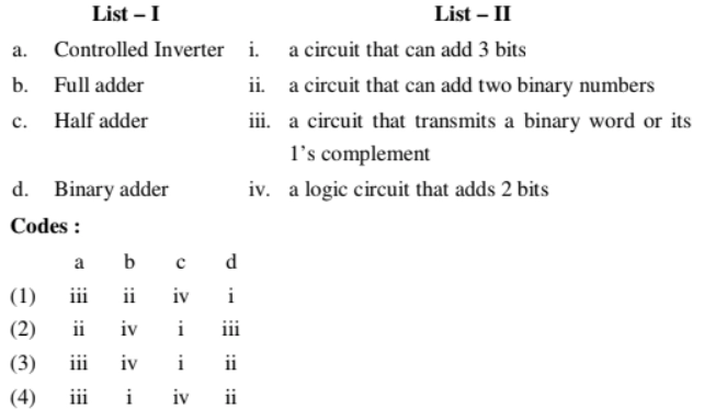
- (1)
- (2)
- (3)
- (4)
Solution: (D) 4
Explanation
A controlled inverter is a circuit that sends a binary message or its 1's complement over the wire. A full adder is a three-bit adding circuit. A logic circuit that adds two bits is known as a half adder. A binary adder is a circuit that allows two binary numbers to be added together. As a result, option (D) is the correct answer.
Question 13: How many 2-input multiplexers are required to construct a 210-input multiplexer?
- 1023
- 31
- 10
- 127
Solution: (A) 1023
Explanation:
Consider the situation where we need to make a 210-input multiplexer out of two-input multiplexers. In the first level, we'll need to set up 29 multiplexers, each of which will accept two inputs (for a total of 210 inputs) and produce one output (hence 29 outputs in total). In the second level, we'll need to set up 28 multiplexers, each of which will accept two inputs (for a total of 29 inputs) and one output (for a total of 27 outputs), and so on. At the tenth level, we must set up a single multiplexer that accepts two inputs and outputs one. Total required number of 2x1 MUX = 29 + 28 + 27 +... + 22 + 1 = 1023 As a result, option (A) is the correct answer.
Question 14: Which of the following is termed as minimum error code
- Binary Code
- Gray Code
- Excess 3 code
- Octal Code
Solution: (B) Gray Code
Explanation
Gray codes, which only change one bit position at a time, are less error-prone for mechanical devices that make and break electrical circuits. As a result, they are regarded as the bare minimum of error codes. Option (B) is the right answer.
Question 15: Because (1)the binary sum of a code and its 9's complement equals 9, the Excess-3 decimal code is self-complementing. (2)It is a code that is weighted. (3) Each bit pattern can be inverted to generate a complement. (4)A code's binary sum plus its 10's complement equals 9.
- (1)
- (2) and (3)
- (1) and (3)
- All the correct
Solution: (C ) (1) and (3)
Explanation
Because the binary sum of a code and its 9's complement equals 9, and complement can be formed by inverting each bit pattern, the Excess-3 decimal code is self-complementing. As a result, option (C) is the correct answer.
Question 16: A multiplexer is put between a group of 32 registers and an accumulator to restrict data transfer such that only one register's content moves to the accumulator at any given moment. The multiplexer requires a number of select lines are _________ .
- 5
- 6
- 4
- 7
Solution: (A) 5
Explanation
A multiplexer can have up to 2m input lines if there are 'm' select lines. There must be log2 (n) select lines = log2 (32) = 5 because there are 32 input lines. The correct answer is (A).
Question 17: The smallest value of m+n for a decoder with m input lines and n output lines that is utilised to uniquely address a byte-addressable 1 KB RAM is __________.
Gate CS 2020
- 18
- 1034
- 10
- 1024
Solution: (B) 1034
Explanation
According to Decoder, we know that we need 210 outputs to map 1 KB RAM. For this we need a 10 × 210 decoder. Therefore,
Here m = 10 and n = 210
Hence,
m + n = 10 + 210 = 10 + 1024 = 1034
Option (B) is correct.
FAQs
Do combinational circuits need memory?
Combinational logic circuits have “no memory”, “timing” or “feedback loops”, their operation is instantaneous. A combinational logic circuit performs an operation assigned logically by a Boolean expression or truth table.
What is a combinational circuit?
A combinational circuit is the digital logic circuit in which the output depends on the combination of inputs at that point of time with total disregard to the past state of the inputs. The digital logic gate is the building block of combinational circuits.
Is flip-flops a combinational circuit?
A flip flop is a sequential circuit that samples its inputs and changes its outputs just once in a while, rather than continually. Instead of being level triggered like latches, flip flops are known to be edge sensitive or edge triggered.
Which is the example of a combinational circuit?
A Combinational Circuit is made up of logic gates whose outputs are decided at any one time only by the current combination of inputs, with no regard for previous inputs. Adder, Subtractor, Converter, and Encoder/Decoder are examples of combinational circuits.
Is latch a combinational circuit?
A basic latch can be made using NOR gates as well as the NAND gates. It is just a simple combinational circuit, then what makes it different is the feedback mechanism that we used.


 8+ registered

