Introduction
Mealy and Moore Machines are among the most fundamental topics as well as the most important ones in the Theory of Computation. In this blog, we will see how to convert a Moore Machine into a Mealy Machine briefly discussing both of them as we move along.
Also Read - Simplification of CFG
Let's first understand some key differences between Moore and the mealy machine before getting deeper into the technique.
Moore Machine
The output of the Moore machine is solely determined by the current state. In this case, if the machine has N states, it will need N flip-flops, where M is the least integer such that N<=2M. If the input string is n characters long, the output string will be n+1 characters long.
Also See, Symbol Table Operations
Mealy Machine
The value of the output function in a Mealy machine is determined by the current state q (t) and the current input i(t). If the machine has ‘N’ states, then N-flip-flops are required, where ‘M’ is the least integer such that N<=2M. If the input string is of length ‘len’, the output string will also be of length ‘len’ in the mealy machine.
Steps for Conversion of Moore To Mealy Machine
Let M1 = {Q,Δ,δ,λ,A} be a Moore Machine, then to construct the equivalent Mealy Machine M2 = {Q1,Δ1,δ1,λ1,A1} proceed as follow:
- Finite set of states for equivalent mealy machine = finite set of states of given Moore machine i.e Q1=Q
- Finite set of input alphabets for resultant mealy machine = finite set of input alphabets given Moore machine i.e Σ = Σ1
- Finite set of output alphabets for resultant Mealy-Machine = Finite set of output alphabets of given Moore machine.
- The output function λ1 is a function of the present state and input symbol
- I.e λ1(Q, A) = (δ(Q , A)) for all states q belongs to Q and input symbol A belongs to Σ
- Start state for the resultant mealy machine = start state of the given Moore machine
Note: It is clear from the above process that only the output function λ1 is different. All other tuples are the same for both the machines.
The two most common methods for converting Moore to Mealy machine are:
- Converting a Moore Machine to Mealy Machine using transition table
- Converting a Moore Machine to Mealy Machine using transition diagram
Conversion of Moore To Mealy Machine using transition table
Example 1 . Find the Mealy Machine equivalent to the following Moore Machine.
| Present state | Next state | Output | |
| 0 | 1 | ||
| A | A | B | 0 |
| B | B | C | 1 |
| C | C | D | 0 |
| D | D | A | 0 |
Solution :
- Finite set of states = A,B,C,D
- Finite set of Input alphabets = 0,1
- Finite set of output alphabets = 0,1
- Start state = A
- Find the output function λ1 for all the states and all the input alphabets

Now draw the transition table corresponding to the above output function
| Next state | ||||
| Input = 0 | Input = 1 | |||
| state | output | state | output | |
| A(Inetial state) | D | 0 | B | 1 |
| B | B | 1 | C | 0 |
| C | C | 0 | D | 0 |
| D | D | 0 | A | 0 |
Conversion of Moore To Mealy Machine using transition diagram
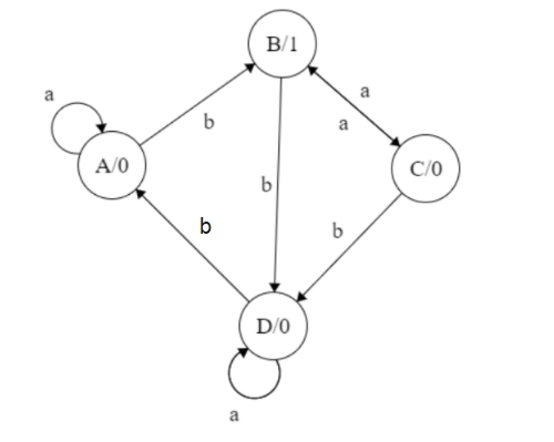
Example 2 : Transition diagram for the Moore Machine is given below.Construct the equivalent transition diagram for the Mealy Machine.

Solution: Transition table corresponding to the above transition diagram:
| Present state | Next state | Output | |
| Input = a | Input = b | ||
| A | A | B | 0 |
| B | C | D | 1 |
| C | B | D | 0 |
| D | D | A | 1 |
- Finite set of states = A,B,C,D
- Finite set of Input alphabets = a,b
- Finite set of output alphabets = 0,1
- Start state = A
- Output function λ1 is given by

Now , construct the transition table corresponding to the above functions
| Present state | Next state | |||
| Input = a | Output | Input = b | Output | |
| A(Initial state) | A | 0 | B | 1 |
| B | C | 0 | D | 1 |
| C | B | 1 | D | 1 |
| D | B | 1 | A | 0 |
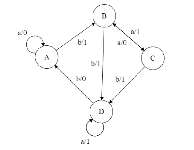
The equivalent transition diagram can be drawn as follows:

It is the required transition diagram for the Mealy Machine. so we have to explore a variety of examples for Conversion of Moore To Mealy Machine.
Also see, Turing Machine in TOC.
Frequently Asked Questions
What is the Transition table?
A transition table is a table that shows how to use the transition function, which takes two arguments and returns a state. The state in which the automaton will be on the input represented by that column is stored in the column. The state of the finite control unit is represented by the row.
What is a transition diagram?
A transition diagram, also known as a state transition diagram, is a directed graph that looks like this: Each state in Q has a node, which is represented by the circle. There is an arrow with no source in the initial state... A double circle indicates accepting states or final states.


