Do you think IIT Guwahati certified course can help you in your career?
Introduction
A counter is a device that keeps track of (and occasionally shows) the number of times a specific event or process has occurred, usually connected to a clock signal. Counters in digital logic are used to count certain events in the circuit. For example, in a UP counter, the count rises with each rising edge of the clock. Not only can a counter count, but it can also follow a specific sequence depending on our design, such as any random sequence 0,1,3,2... These designs can be created using flip-flops.
Ring Counter
A ring counter is a specific sort of Serial IN Serial OUT Shift register application. The main difference between the shift registers and the ring counters in digital logic is that the shift register uses the last flip flop result as the output. However, this result is supplied as an input to the first flip flop in the ring counter. Everything else in the ring counter is identical to what's in the shift register.
In a Ring counter,
No. of states in Ring counter = No. of flip-flop used.
State Diagram
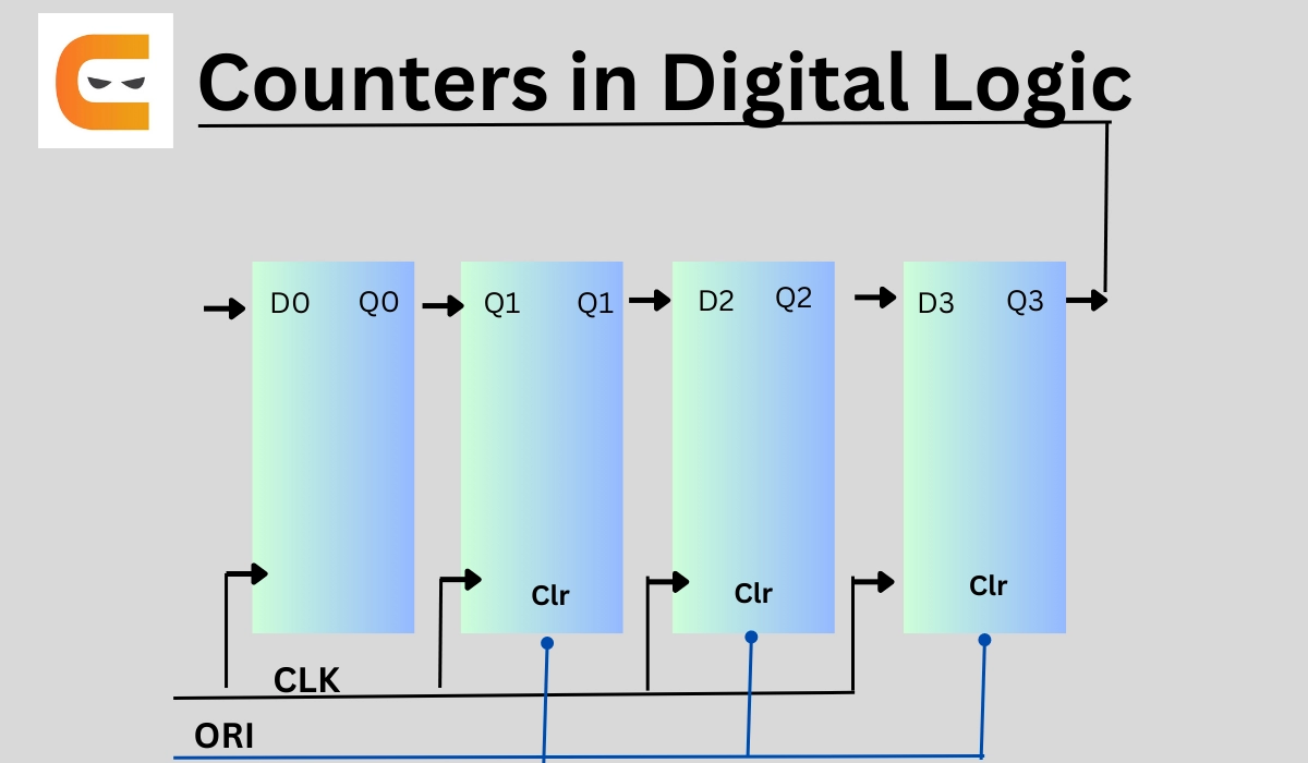
Block Diagram of a Ring Counter
We're using four D flip-flops here. The same clock pulse is sent to the clock input of all the flip flops as a synchronous counter. This circuit is designed using the Overriding input (ORI).
The Overriding input is clear and preset.
What's happening here
When the preset (PR) is 0, the output is 1. When the clear (CLR) parameter is set to 0, the output is 0. Because PR and CLR are active low signals, they always work in the value 0 range.
These two values (always the same) are unaffected by the input D or the Clock pulse (CLK).
Working
The ORI input is connected to the PR input of the first flip flop, FF-0, and the clear inputs of the other three flip flops, FF-1, FF-2, and FF-3. For the initial flip flop, the preset input is set to 0. As a result, the first flip flop's output is one, while the following flip flops' outputs are zero. Preset 1 is the output of the first flip flop, which is used to construct the ring in the ring counter.
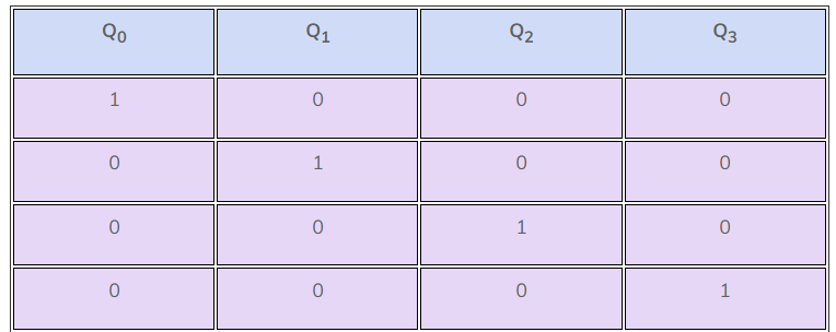
Truth table
This Preset 1 is created by lowering the ORI value and setting the time Clock (CLK) to don't care(X). After that, the ORI was set to high, and a low clock pulse signal was applied as the clock (CLK) was triggered on the negative edge. The preset 1 is then transferred to the next flip-flop with each clock pulse, forming a Ring.
We may deduce from the preceding table that the 4-bit Ring Counter has four states:
Types of Ring Counter
Straight Ring Counter
A straight Ring Counter is also known as One hot counter. The result of the previous flip-flop is used as an input to the first flip-flop. The ORI input is connected to the PR input of the first flip flop and the clear input of the other flip flops in the ring counter.
Twisted Ring Counter
It's also known as a Johnson counter, a switch-tail ring counter, or a walking ring counter. It circulates a stream of ones followed by zeros around the ring by connecting the complement of the output of the final shift register to the input of the first register.
Binary Counter
A binary counter connects several flip-flop circuits. The flip-flops change state with every clock pulse, producing a binary number for digital timers. Binary synchronous counters in digital logic eliminate the settling time issue of ripple counters. These counters use count pulses. This counter is sometimes known as a "ripple through" counter.
All flip-flops's control inputs Clk are connected directly. A 4-bit binary counter's state and block diagram are given below:
State Diagram
As demonstrated below, a 4-bit binary synchronous counter with count enable function may be implemented:
Block Diagram of a Binary Counter
Working
Each flip-flop's J and K inputs are set to 1 to create a toggle at each clock input cycle. A toggle is made in the second cell for every two toggles in the first cell and so on down to the fourth cell. This yields a binary number equal to the input clock signal's number of cycles.
Truth Table
Decimal
X3
X2
X1
X0
0
0
0
0
0
1
0
0
0
1
2
0
0
1
0
3
0
0
1
1
4
0
1
0
0
5
0
1
0
1
6
0
1
1
0
7
0
1
1
1
8
1
0
0
0
9
1
0
0
1
10
1
0
1
0
11
1
0
1
1
12
1
1
0
0
13
1
1
0
1
14
1
1
1
0
15
1
1
1
1
Back to 0
0
0
0
0
Johnson Counter
The Ring counter and the Johnson counter are pretty similar. The main difference between the Johnson counters and the ring counters in digital logic is that the last flip flop's result is supplied as an input to the first flip flop. The inverted outcome Q' of the last flip flop, on the other hand, is provided as an input in the Johnson counter. The Johnson counter's remaining tasks are similar to a ring counter. The Creeping counter is another name for the Johnson counter.
In a Johnson Counter,
No. of states in Johnson counter = No. of flip-flops used
Number of used states = 2n
Number of unused states = 2n - 2*n
State Diagram
Block Diagram of a Johnson Counter
The 4-bit Johnson counter uses four D flip flops, similar to the Ring counter, and the same clock pulse is applied to all of the flip flops' inputs.
Truth Table
Ripple Counter
A ripple counter is an asynchronous counter in which the clock pulse ripples through the circuit. The n-MOD ripple counter is created by mixing n flip-flops. The n-MOD ripple counter may count 2n states before resetting to its starting value.
State Diagram
Block Diagram of a Ripple Counter
What's Happening here
The circuit of a binary ripple counter is depicted in the diagram above. J0K0 and J1K1 are the two JK flip flops used here. Flip flops' JK inputs are provided with a high voltage signal that keeps them in state 1. The symbol representing the clock pulse shows a negative triggered clock pulse. The output Q0 of the first flip flop is applied as a clock pulse to the second flip flop, as shown in the diagram.
Truth Table
The fourth condition of the JK flip flop happens when high voltage is applied to the inputs of the flip flops. When we supply high voltage to the input, the flip-flops will be in state 1. As a result, at the negative going end of the clock pulse, the states of the flip flips passes are toggled.
Here's the truth table of the J-K flip flop for relativity.
Working
When the negative clock edge passes through the flip flop, the state of the output Q0 changes. All of the flip-flops are initially set to 0. These flip-flops change states when the passed clock goes from 1 to 0. When the inputs of the flip flops are all one, the JK flip flop toggles, changing its state from 0 to 1. The procedure is the same for all clock pulses.
The clock pulse from the first flip flop is sent to the second. The state of the second flip flop is changed when the output Q0 transitions from 1 to 0. Q0 and Q1 are treated as LSB and MSB, respectively. The counter keeps track of the numbers 00, 01, 10, and 11. After counting these figures, the counter resets itself and begins counting anew from 00, 01, 10, and 1. Count values until clock pulses are sent to the J0K0 flip flop.
A counter is a device in digital logic that keeps track of (and occasionally shows) the number of times a specific event or process has occurred, usually connected to a clock signal. It helps maintain the process synchronisation.
What are ring counters and Johnson counters?
A ring counter is a specific Serial IN Serial OUT Shift register application. The Ring counter and the Johnson counter are pretty similar. The main difference between the Johnson and ring counters in digital logic is that the last flip-flop's result is supplied as input to the first flip-flop.
Why JK flip flop is used in counters?
In digital logic designing, the JK flip-flops are used in counters. Using a JK flip-flop is important because, based on the clock pulse, it can change its state if both inputs are high.
Which IC is used in the ring counter?
The term "integrated circuit" (abbreviated as "IC") refers to any semiconductor-based chip that contains an integrated collection of digital circuitry. The IC components required for ring counters are IC 74164 and IC 7404.
Conclusion
In this article, we have extensively discussed four main counters in digital logic, with how they are built and work along with the truth table curated upon the input signal provided to the flip flops used in the counters in digital logic.
We hope that this blog has helped you enhance your knowledge regarding counters used in digital logic and if you would like to learn more, check out our articles on Code Studio. Do upvote our blog to help other ninjas grow. Happy Coding!
Live masterclass
Resume & linkedin tips to crack Amazon GenAI Interviews
by Anubhav Sinha
30 Jul, 2026
12:30 PM
Master PowerBI using Flipkart Dataset & Ace 20LPA+ Data Roles
by Prerita Agarwal
27 Jul, 2026
12:30 PM
Multi-Agent AI Support Bot using OpenAI & Gemini
by Saurav Prateek
28 Jul, 2026
12:30 PM
Zomato Data Analysis Case Study: Ace 25L+ Roles in FoodTech(no use)
by Abhishek Soni
29 Jul, 2026
11:30 AM
Zomato Sales Analytics: SQL + PowerBI for 25LPA Jobs
by Abhishek Soni
29 Jul, 2026
11:30 AM
Resume & linkedin tips to crack Amazon GenAI Interviews
by Anubhav Sinha
30 Jul, 2026
12:30 PM
Master PowerBI using Flipkart Dataset & Ace 20LPA+ Data Roles


 9+ registered