Do you think IIT Guwahati certified course can help you in your career?
Introduction
Flip-flops are bistable logic circuits used for storing binary data. They have two stable states and change output based on input signals, making them essential for memory and sequential logic applications.
A latch is a type of logical circuit. It has two stable states: low and high. Although latches and flip-flops are basic storage elements, they operate differently. Flip flops consist of the following types: SR Flip Flop, JK Flip Flop, D Flip Flop, and T Flip Flop. This article will explain about D Flip Flop.
What is D Flip Flop?
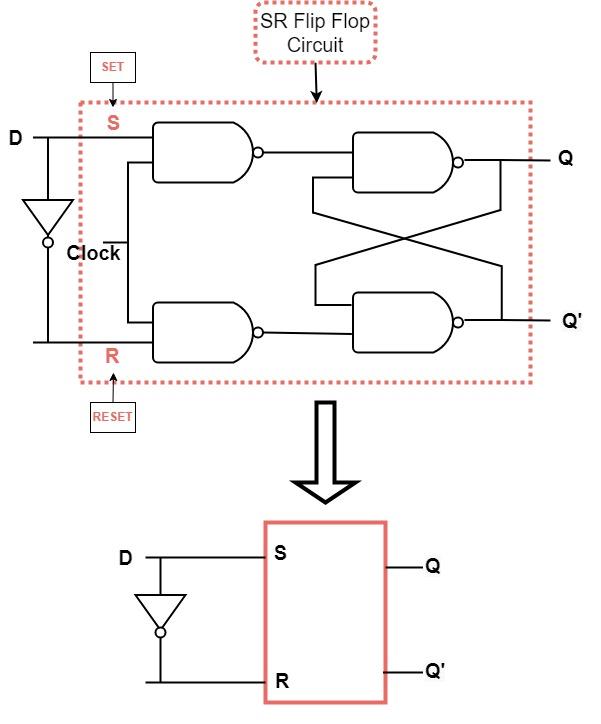
The undefined input condition of SET = "0" or RESET = "0" is prohibited in SR NAND Gate Bistable circuit. SR flip-flops suffer from this drawback. To counteract this, we need an inverter. Inverters are connected between the Set and Reset inputs to form another flip-flop circuit called D flip flops.
D flip-flops can be constructed with a NAND gate or a NOR gate. They are available as integrated circuits because of their versatility. Typically, D flip-flops introduce a delay in timing circuits, like buffers and sample data at specific intervals. In comparison with JK flip-flops, a D flip-flop requires fewer wiring connections.
In flip-flops, a D-type flip-flop has two stable states clocked together. This flip-flop is also called "data" or "delay" flip-flop. Flip-flops of the D-type have a delay of one clock cycle in their input. Combining several D-type flip-flops makes it possible to create delay circuits used in many applications.
Working of D Flip-Flop
A D Flip-Flop stores data and transfers it based on a clock signal. It ensures that the output follows the input (D) only when the clock edge occurs.
How It Works
Input (D): The flip-flop stores the value of D.
Clock (CLK): The output updates only when the clock edge (rising or falling) occurs.
Output (Q, Q’):
If D is 1 when the clock triggers, Q becomes 1.
If D is 0, Q becomes 0.
Q' is always the opposite of Q.
Representation of D Flip-Flop using Logic Gates
A D-type flip-flop consists of four inputs, which are: Data input, Clock input, Set input, and reset input. There are also two outputs, which are logically inverse to each other. Depending on the logic input, either low or high voltage is used. To synchronize the circuit with external signals, the clock input is used.
The Truth Table for D Flip-Flop
Input cannot affect the output status when the clock signal is LOW. If the clock is high, the inputs become active. The D flip-flop is a controlled bistable latch with the clock signal as the control signal. The edge-triggered D flip-flops here fall into positive edge-triggered and negative edge-triggered. Therefore, according to the inputs, there are two stable output states.
This truth table shows how various combinations of inputs affect the output of a logic circuit.
Clock
Input
Output
D
Q
(Present state)
Qn+1
(next state)
↓ LOW(0)
x
Q
1
↑ HIGH(1)
0
0
1
↑HIGH(1)
1
1
0
Taking into account, D-type flip-flops are edge-triggered ↓and ↑ indicate the direction of the clock pulse.
The D flip-flop's input state is D(Data). Q and Qn+1 represent output states. The output changes according to the inputs in the table. In addition, remember that all of these scenarios are only possible when the clock signal is present. This works like an SR flip-flop when used with the complementary inputs only.
Characteristics Table for D Flip Flop
According to flip-flop input and current state, it defines the next state of a flip-flop.
Input 1(Qn)
Input 2(D)
Output(Qn+1)
0
0
0
0
1
1
1
0
0
1
1
1
Since (Qn+1) is similar to input D regardless of whether Q is identical to 0 or 1, the next state of the flip-flop is independent of the current state.
The input pulse will modify the flip-flop's output regardless of earlier output, as long as the input pulse is applied to input D.
So we have concluded that Qn+1=D.
Characteristic Equation of D Flip-Flop
The characteristic equation of a D Flip-Flop defines its behavior by expressing the next state (Qₙ₊₁) in terms of the current input (D) and clock signal.
Formula:
This means that the next state (Qₙ₊₁) of the flip-flop directly follows the input D at the triggering edge of the clock signal.
Explanation:
If D = 1, the next state Qₙ₊₁ becomes 1.
If D = 0, the next state Qₙ₊₁ becomes 0.
The output updates only when the clock edge occurs.
Key Points:
The D Flip-Flop eliminates uncertainty by ensuring the output strictly follows D.
It is widely used in data storage, registers, and synchronous circuits.
The equation Qₙ₊₁ = D makes it the simplest and most predictable flip-flop type.
This characteristic equation helps in designing sequential circuits and ensuring reliable data transfer in digital systems.
Excitation Table for D Flip Flop
As a function of the current and next states, it defines the flip-flop input variable.
Input 1(Qn)
Input 2(Qn+1)
Output(D)
0
0
0
0
1
1
1
0
0
1
1
1
The excitation input D = 0 is required for the state transition from Qn = 0 to Qn+1 = 0, regardless of Qn value.
When Qn = 0 and Qn+1 = 1, the input required for excitation is D = 1.
For input D = 0, the state transitions from Qn = 1 to Qn+1 = 0.
When D=1, the state transition is from Qn = 1 to Qn+1 = 1.
To generate the excitation table, all of the states mentioned above transitions for D flip-flop from the current state(Qn) to the next state(Qn+1) for the corresponding excitation inputs will be filled in the table above as output(D).
An SR flip-flop stores data using Set (S) and Reset (R) inputs, while a D flip-flop transfers input (D) to output on a clock edge.
Why is the D flip-flop called delay?
The D flip-flop is called a delay flip-flop because it transfers the input (D) to output (Q) after a clock pulse, introducing a controlled delay.
What is the use of the clock in D flip-flop?
The clock signal controls when the D flip-flop updates its output, ensuring data changes only at a specific clock edge for synchronization.
What is the principle of D flip-flop?
A D flip-flop follows the principle of data storage, where the output Q copies the input D only at the active clock edge.
What is the standard form of D flip-flop?
Essentially, D Type flip-flops are high-activated S-R flip-flops with an additional inverter to prevent their inputs from both being high or both being low simultaneously. With these simple modifications, the SR flip-flop is prevented from reaching indeterminate and non-allowed states.
Conclusion
In this article, we discussed the D Flip-Flop, a fundamental sequential circuit used in digital electronics. It plays a crucial role in data storage and synchronization by capturing input data on the clock edge. With its simple design and ability to eliminate metastability, the D Flip-Flop is widely used in registers, memory units, and digital systems. Understanding its working principle helps in designing efficient and reliable digital circuits.


 8+ registered

