Do you think IIT Guwahati certified course can help you in your career?
Introduction
In a Computer Network, a sender and a receiver exist to exchange data via some connection. Some protocols ensure that the receiver understands the data sent by the sender. Many functionalities, namely error control, flow-control, encryption/decryption, etc., are used in this two-way communication. These functionalities are grouped in a standardized model, namely the OSI model (Open System Interconnect). This model is divided into various layers, as given below.
In this blog, we will discuss only the data link controls. The data link control is used to provide the building blocks for communication across various physical media. It connects upper processes to the physical layer. Data link control places data on and receives data from the network, providing data delivery between Ethernet devices.
Hop-to-hop delivery is also called node-to-node delivery, which means that hop-to-hop transport involves both source and destination nodes and all the intermediate nodes. It allows data to be forwarded between the source and destination even if the path is not correctly connected during the communication.
Here there are two networks, say A and B. In each network, nodes are connected using some topology. If we want to transfer data from network A to network B, say from A4 to B1, then the data does not travel directly from A4 to B1. It is the responsibility of the data link layer to track node-to-node delivery, i.e., the very first destination of the packet from A4 is to R1, then R2, and then finally B1.
Flow Control
This is the method to control the flow of data at every node. The destination node will always be overloaded with packets if this is not checked.
Three protocols which are used are
1.Stop And Wait
This protocol for sending the data packet waits for acknowledgment. The following data packet is sent only when the sender receives the acknowledgment.
Problems here are
If the sender does not receive the acknowledgment, say acknowledgment is lost, then the sender will wait for some time (time out timer) and send the frame again. The sequence number is maintained so that repeated frames are not in process.
In the Go Back N protocol, we receive a cumulative acknowledgment. Here, we have an acknowledgment timer, i.e., after each fixed time, cumulative acknowledgment is sent. The sequence number is modulo 2^m, where m is the size of the sequence number field in bits.
Here sender window size is 2^m-1, and the receiver window size is 1.
Here, N number of packets are sent each time by the sender, and the receiver receives one at a time and acknowledges. In this protocol, if one frame is corrupted, then all the previous N frames are to be resent, and the receiver keeps track of only one frame. This process uses more bandwidth and slows down the transmission, and to overcome this problem, we use selective repeat.
Here, only corrupted or damaged frame is resent. Here both sender and receiver window size is 2^(m-1).
Since here, frame 0 and frame 1 have been acknowledged, so when frame 2 is lost, we resent frames starting from 2 only.
Error Control
Error control is the process of detecting and correcting the data frames that are corrupted or lost during the transmission. In the case of lost or corrupted frames, the receiver does not receive the correct data frame, and the sender is ignorant about the loss.
The following are the two methods used to detect and correct the error.
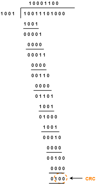
Cyclic redundancy check: This method uses modulo-2 division. If the remainder found is 0, then the data is not corrupted; else, the data is corrupted.
Say, for example,
Data-10001100
Generator-1001
Firstly,( the number of bits in data - 1) zeroes are appended to the generator and then proceeded with modulo-2 division.
2. Checksum:
Here, the sum is calculated and checked if we receive 0 as the answer. If our answer is anything other than 0, then this means that the data is corrupted.
You can read related articles such as Congestion Control in Computer Networks here.
Framing
Frames are the collection of bits. Framing means transferring frames from source to destination and vice versa.
We need framing in the data link layer because the data link layer takes packets from the network layer and compressed them into frames. If the frame size is too large then the packet size is further divided into small frames. As the small-sized frames make the flow and error control more efficient.
This can be done using three methods:
Character count
Character/ byte stuffing
Bit stuffing
Character count
Here, the first figure depicts the sender’s site. There are 4 frames. The first bit of each frame gives the length of that frame, including itself. Frame 1 has 5 characters, as the first bit depicts, frame 2 has 5 characters, frame 3 has 8, and so on.
The second figure depicts the receiver’s site. Here the first frame receives 5 bits, but in the second frame, due to some corruption, it changes to 7, which changes the entire thing. Now, frame 2 will have 7 bits. This method does not provide synchronisation. This method was used in older times, and nowadays it is not used.
Byte Stuffing
In this method, before each special flag, say ESC or FLAG, a special ESC character is stuffed, as seen in the figure. Here we are inserting a byte or character in the message. Whenever the receiver reads the message, it removes the stuffed character and reads it.
Bit stuffing
Here, a sender stuffs a bit.
Say if we have 5 continuous 1’s, then after the 4th one, a 0 is stuffed.
Example: 0011111110111110110
Solution: 001111011101111010110
Till now, I assume you must have got a basic idea about data link controls.
Cumulative acknowledgment is when we send a group of packets to the receiver and receive a single acknowledgment consisting of information of all data packets sent. Independent acknowledgment is one when we receive acknowledgment of each packet individually.
What is modulo-2 division?
The modulo-2 division is the same as a binary division, except that we perform XOR operations instead of subtracting.
A
B
A XOR B
0
0
0
0
1
1
1
0
1
1
1
0
Why is data transmission necessary?
Data transmission is essential because an enormous amount of data and many complex tasks are to be performed. So if we don’t understand the concept behind this, we cannot figure out the best performance, causing a system lag.
Conclusion
This article taught us about data link controls. We discussed the different responsibilities of the data link layer.
We hope you could easily take away all critical and conceptual techniques by walking over the given examples.
Now, we strongly recommend you understand the other related concepts in Computer Networks and enhance your learning. You can get a wide range of topics similar to this on Computer Network.


 8+ registered

