Do you think IIT Guwahati certified course can help you in your career?
Introduction
Digital electronics is the field of study where complex data is transformed into a language of 0 and 1, a language only our devices can understand. Many devices are used in digital electronics to control the signal input and output, like resistors, counters, capacitors, multiplexers, transformers, decoders, encoders, etc.
The decoder in Digital Electronics helps convert binary code into a set of signals. In this article, we will be discussing the types of Decoders, their uses, advantages, and disadvantages of decoders in Digital Electronics.
What are Decoders in Digital Electronics?
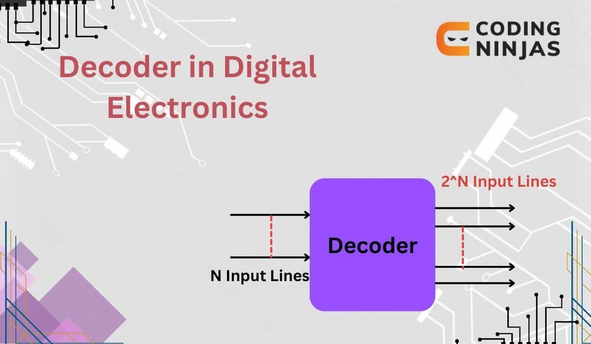
A Decoder in Digital Electronics is an important device used to convert binary code into a set of signals. It can be used to convert binary signals to octal or hexadecimal code.
Decoders accept n input signals and produce 2^n output signals. Hence the size of the decoder is nx2n, for example, 3x8. Here the input code contains fewer bits than the output code. It uses a set of NAND, OR, NOR, AND, and NOT gates.
There are mainly three different types of Decoder in Digital Electronics. Let us look at each of them one by one.
2 to 4 line Decoder
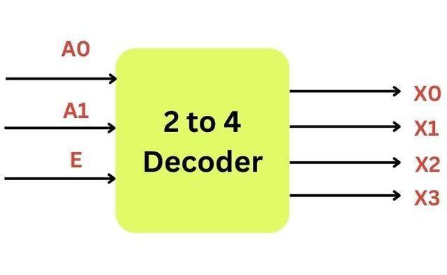
There are two inputs (A0, A1) and an Enable (E) in 4 to 2 line decoders which, after decoding, give four outputs (X0, X1, X2, and X3). Based on the inputs, one of the outputs will be active. This decoder is made up of four AND gates.
Block Diagram
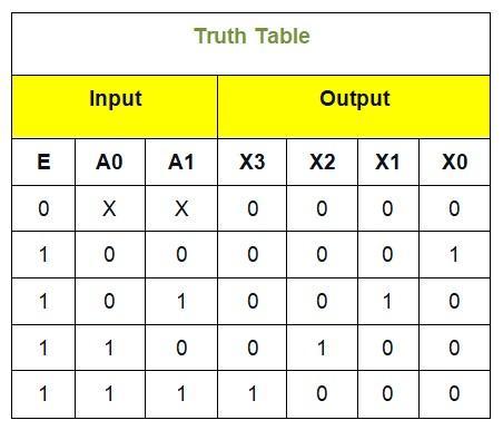
Truth Table
Logical Expression
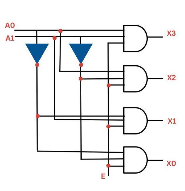
X3=E.A1.A0
X2=E.A1.A0’
X1=E.A1’.A0
X0=E.A1’.A0’
Logic Circuit Diagram
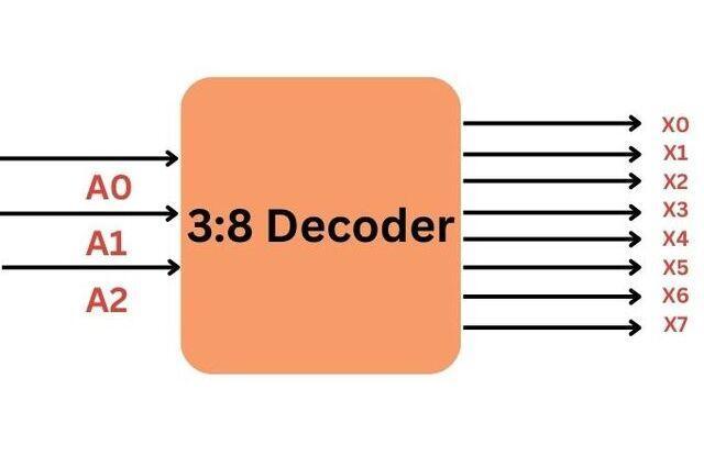
3 to 8 line Decoder
There are three input (A0, A1, and A2) and eight output lines (X0, X1, X3, X4, X5, X6, X7) in 8 to 3 line decoder in digital electronics. This decoder is used to perform conversions on 3 bit binary code. Among the eight outputs, only one is set to true or active at any time, while the others are set to false. The 3 to 8 line decoder is called the Binary to Octal decoder in Digital Electronics.
Block diagram
Truth Table
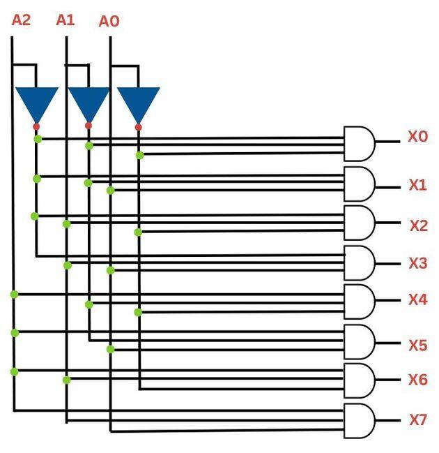
Logical expression:
X0=A0'.A1'.A2'
X1=A0.A1'.A2'
X2=A0'.A1.A2'
X3=A0.A1.A2'
X4=A0'.A1'.A2
X5=A0.A1'.A2
X6=A0'.A1.A2
X7=A0.A1.A2
Logic circuit Diagram
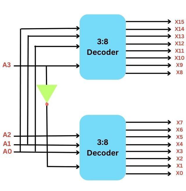
4 to 16 line Decoder
There are four inputs (A0, A1, and A2) and sixteen output lines (X0, X1, X3, X4, X5, X6, X7….., X15) in 4 to 16 line decoders. It can be built using a 3 to 8 or 2 to 4 decoder.
Block Diagram
Truth Table
Logic Circuit Diagram
Applications of Decoder in Digital Electronics
Decoders are essential components in digital electronics with various applications:
Address Decoding: In computer memory systems, decoders are used to select specific memory locations based on the address provided by the CPU.
Display Multiplexing: Decoders are employed to control multiplexed displays by selecting which segment or digit to activate based on the input.
Data Demultiplexing: Decoders can be used to demultiplex data from multiple sources to select the desired input based on the control signal.
Binary to Decimal Conversion: Decoders can convert binary-coded decimal (BCD) input into its corresponding decimal output by activating the appropriate output based on the input.
Seven-Segment Display Driving: Decoders drive seven-segment displays by converting binary input into the appropriate segment signals to display decimal digits.
Control Logic: Decoders are often used in control logic circuits to decode input signals and generate control signals for various system components.
Uses Of Decoders Digital Electronics
The uses of Decoder in Digital Electronics are:
Binary decoders are an important device in addressing decoding circuits, which are used to generate chip-select circuits.
They are used in computer systems to select specific memory locations from a range of memory addresses.
They are used in digital communication systems. Here decoders are used to decode the digital data received over communication signals.
They are used to identify and correct errors in digital data.
Advantages of using Decoders in Digital Electronics
The advantages of Decoder in Digital Electronics are:
Binary Decoders are used to convert an input signal into many parallel outputs. This, in turn, increases the performance of the system.
It allows us to select one output among the many based on the input code. This increases the flexibility of the system.
Binary Decoders help in distributing the data from a single input to many outputs. This reduces the probability of errors and also increases the reliability.
Disadvantages of using Decoders in Digital Electronics
The disadvantages of Decoder in digital electronics are:
They have a more complex structure than the demultiplexers. They require extra logic gates to give correct results.
They are used to convert binary codes into their respective outputs. That is, they are limited to specific uses only.
The number of outputs in a binary decoder is fixed. This becomes difficult when the user needs to address more outputs.
Frequently Asked Questions
What is the difference between an encoder and a decoder?
While encoders are used to convert data into binary code, the decoder accepts binary code to give the original data. Octal to binary encoder is an example of an encoder, while a Binary to Octal encoder is an example of a decoder.
What is a decoder in digital electronics?
A decoder in digital electronics is a combinational circuit that converts binary input into a unique output based on the input code, activating one of several output lines.
What are the different types of decoders?
The different types of decoders include Binary Decoder, BCD Decoder, Priority Decoder, Address Decoder and Seven-Segment Decoder.
What is an encoder in digital electronics?
An encoder in digital electronics is a combinational circuit that converts multiple input lines into a smaller number of output lines, typically with fewer bits, preserving the original data.
What is the working principle of a decoder?
A decoder is a combinational circuit that converts binary input into a unique output. It activates one output among 2^n lines using logic gates. Common applications include memory address decoding, seven-segment displays, and microprocessors. A 2-to-4 decoder maps two inputs to four outputs uniquely.
Where is decoder used?
Decoders are used in various applications in digital electronics, including Address decoding in memory systems, Display multiplexing in digital displays, Data demultiplexing in communication systems and Control logic generation in digital circuits
Conclusion
A Decoder in Digital Electronics is a very important device used to convert binary data into a parallel set of signals.We hope this blog has helped you understand the concept of a Decoder in Digital Electronics better.
We suggest you read some of our other articles related to digital electronics:


 9+ registered