Introduction
A combinational circuit is a circuit in which we combine the different gates in the circuit. For example, decoder, encoder, multiplexer and Demultiplexer.
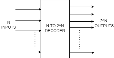
In this article, we will look at a decoder, which is a combinational circuit that converts binary data from N coded inputs to a maximum of 2^N different outputs. It is the opposite of the encoder.
Recommended Topic, 8085 Microprocessor Pin Diagram and Difference Between Jfet and Mosfet
Decoder
It is a combinational circuit that converts the N coded input to 2^N coded output. To keep things simple, only one input line is initiated. The binary information is comparable to the 2^N-bit output code. The operation of the decoder is completely the reverse of the encoder.
A digital decoder transfigures a set of digital input signals into a similar decimal code at its output, as the word "decoder" means "to translate or decode coded information from one format into another".
Binary Decoder
A binary decoder is a kind of digital logic device that upholds inputs of 2-bit, 3-bit, or 4-bit codes depending on the number of data input lines; hence a decoder with two or more bits is known as having an n-bit code.
A Binary Decoder transforms coded inputs into coded outputs in which the input and output codes are different, and decoders can "decode" either a Binary or BCD (8421 code) input pattern to a Decimal output code.
2:4, 3:8, and 4:16 line arrangements are common "binary decoder" circuits.
2:4 Binary Decoder
The 2:4 line binary decoder shown below involves two inputs named Q0, Q1 and four outputs P0, P1, P2 and P3. The two binary inputs, Q0 and Q1, are decoded into one of four outputs; thus, they describe a 2:4 binary decoder. Each output represents one of the two input variables' minterms (each output = a minterm).

The truth table for the 2:4 decoder is as follows:

Logical Expression for P3, P2, P1 and P0
P3= Q1Q0
P2= Q0Q1’
P1= Q0’Q1
P0= Q0’Q1’
These four Boolean functions P3, P2, P1 and P0 described above can be implemented using an array of four AND gates.

Recommended Topic, Microinstruction in Computer Architecture
3:8 Binary Decoder
The 3:8 line decoder shown below involves three inputs named Q0, Q1, Q2 and Eight outputs P0, P1, P2, P3, P4, P5, P6 and P7. The three binary inputs, Q0, Q1 and Q2, are decoded into one of eight outputs; thus, they describe a 3:8 binary decoder. Each output represents one of the three input variables' minterms (each output = a minterm).

The truth table for the 3:8 decoder is as follows:

Logical Expression for P7, P6, P5, P4, P3, P2, P1 and P0
P0= Q0’Q1’Q2’
P1= Q0’Q1’Q2
P2= Q0’Q1Q2’
P3= Q0’Q1Q2
P4= Q0Q1’Q2’
P5= Q0Q1’Q2
P6= Q0Q1Q2’
P7= Q0Q1Q2
The implementation of these eight boolean functions are as follows:
1. By using eight AND gates

2. Using a 2-to-4 decoder
We can find the number of lower-order decoders required to implement a higher-order decoder using the following formula.
Required no. of lower-order decoder= W2/W1
Here,
W1= Number of output in lower-order decode.
W2= Number of output in higher-order decoder.
W1= 4
W2= 8
Required no. of 2-to-4 decoder= 8/4 =2
i.e Two 2-to-4 decoders are required in implementing 3:8 decoder.


 9+ registered