Do you think IIT Guwahati certified course can help you in your career?
Introduction
Digital Electronics, a field focusing on electrical circuits designed to process and manage digital signals, primarily operates on binary logic, using '0' and '1' to represent these signals. Various components like capacitors, resistors, multiplexers, and more play crucial roles in this domain. Among these, an encoder is a pivotal element in digital electronics.
An encoder in digital electronics is a specialized circuit that transforms binary inputs into a distinct binary code. This code is representative of the input's position, effectively identifying which specific input is active at any given time. The unique capability of encoders to convert parallel input sets into serial binary codes makes them indispensable in many digital systems. Their application ranges from simplifying data processing to enhancing the efficiency of signal transmission, thereby making them a cornerstone component in digital electronic designs.
In this article, we will be discussing the types of encoders, their uses, advantages, and disadvantages of Encoder in Digital Electronics.
What is Encoders in Digital Electronics?
Encoder in Digital Electronics are an important device used to process and convert data. They accept many input signals (binary information in the form of 2^N input lines) and convert them into a special code. It accepts many input lines to produce a smaller number of output lines.
Encoders allow efficient communication between the different parts of the digital circuit. They are used in address decoding, data conversion, multiplexing, etc.
Types of encoders
There are mainly four different types of Encoder in Digital Electronics. Let us look at each of them one by one.
4 to 2 Line Encoder
8 to 3 Line Encoder (Octal to Binary Encoder)
Decimal to BCD Encoder
4 to 2 Line Priority Encoder
1.4 to 2 line encoder
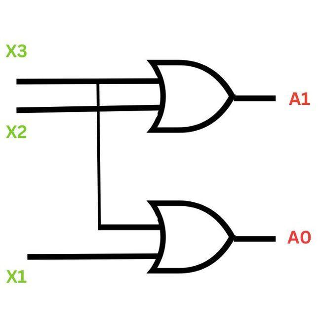
There are four inputs (X0, X1, X3, X4) in 4 to 2 line encoders which, after encoding, give two outputs (A0 and A1). Among the four inputs, only one is set to true at any point in time, while the other three are set to false. The encoder detects which input data is true and then gives the output at A0 and A1. The block diagram and truth table will help you understand the working of the encoder better.
Block Diagram
Truth Table
Truth Table
Inputs
Outputs
X3
X2
X1
X0
A1
A0
1
0
0
0
0
0
0
1
0
0
0
1
0
0
1
0
1
0
0
0
0
1
1
1
Logical Expression:
A0=X3+X1
A1=X3+X2
Logic Gate Diagram
2.8 to 3 line encoder
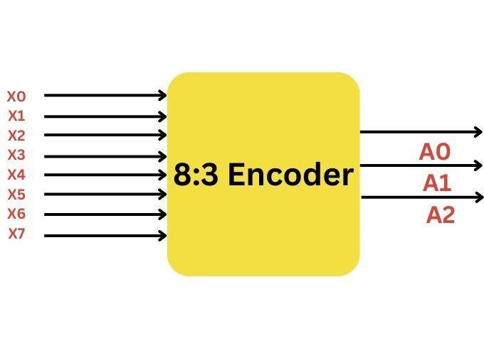
There are eight inputs (X0, X1, X3, X4, X5, X6, X7) in 8 to 3 line encoders which, after encoding, give three output signals (A0, A1, and A2). Among the eight inputs, only one is set to true or active at any time, while the others are set to false. The encoder detects which input data is true and then gives the results at A0, A1, and A2. The 8 to 3-line encoder is called the Octal to Binary Encoder in Digital Electronics. The block diagram and truth table given below will help you understand the working of the encoder better.
Block Diagram
Truth Table
Truth table
Inputs
Outputs
X0
X1
X2
X3
X4
X5
X6
X7
A2
A1
A0
1
0
0
0
0
0
0
0
0
0
0
0
1
0
0
0
0
0
0
0
0
1
0
0
1
0
0
0
0
0
0
1
0
0
0
0
1
0
0
0
0
0
`1
0
0
0
0
0
1
0
0
0
1
0
0
0
0
0
0
0
1
0
0
1
0
1
0
0
0
0
0
0
1
0
1
1
0
0
0
0
0
0
0
0
1
1
1
1
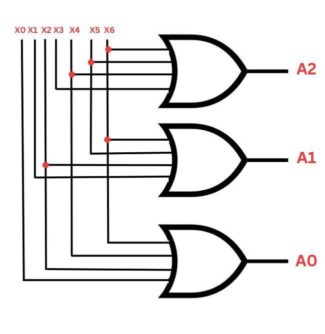
Logical expression:
A2=X4+X5+X6+X7
A1=X2+X3+X6+X7
A0=X7+X5+X3+X1
Logic Gate Diagram
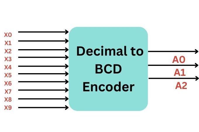
Decimal to BCD encoder
There are ten inputs (X0, X1, X3, X4, X5, X6, X7) in Decimal to BCD line encoders which, after encoding, give four output signals (A0, A1, A2, and A3). Among the ten inputs, only one is set to true or active at any time, while the others are set to false. The encoder detects which input data is true and then gives the results at A0, A1, A2, and A3. Let us understand the working of the encoder better with the help of the block diagram and truth table given below.
Block Diagram
Truth Table
Truth table
Inputs
Outputs
X0
X1
X2
X3
X4
X5
X6
X7
X8
X9
A3
A2
A1
A0
1
0
0
0
0
0
0
0
0
0
0
0
0
0
0
1
0
0
0
0
0
0
0
0
0
0
0
1
0
0
1
0
0
0
0
0
0
0
0
0
1
0
0
0
0
1
0
0
0
0
0
0
0
0
`1
0
0
0
0
0
1
0
0
0
0
0
0
1
0
0
0
0
0
0
0
1
0
0
0
0
0
1
0
1
0
0
0
0
0
0
1
0
0
0
0
1
1
0
0
0
0
0
0
0
0
1
0
0
0
1
1
1
0
0
0
0
0
0
0
0
1
0
1
0
0
0
0
0
0
0
0
0
0
0
0
1
1
0
0
1
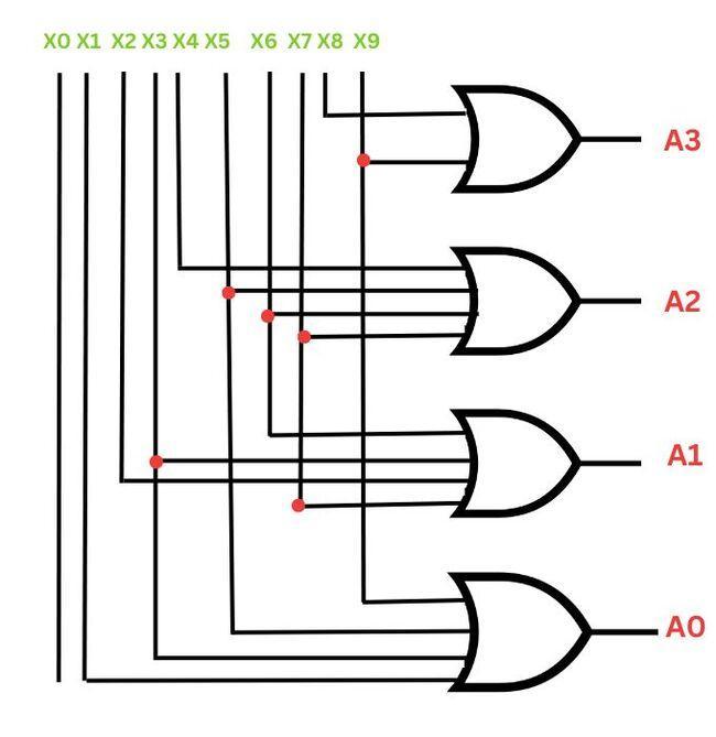
Logical expression:
A3 = X9 + X8
A2 = X7 + X6 + X5 +X4
A1 = X7 + X6 + X3 +X2
A0 = X9 + X7 +X5 +X3 + X1
Logic Gate Diagram
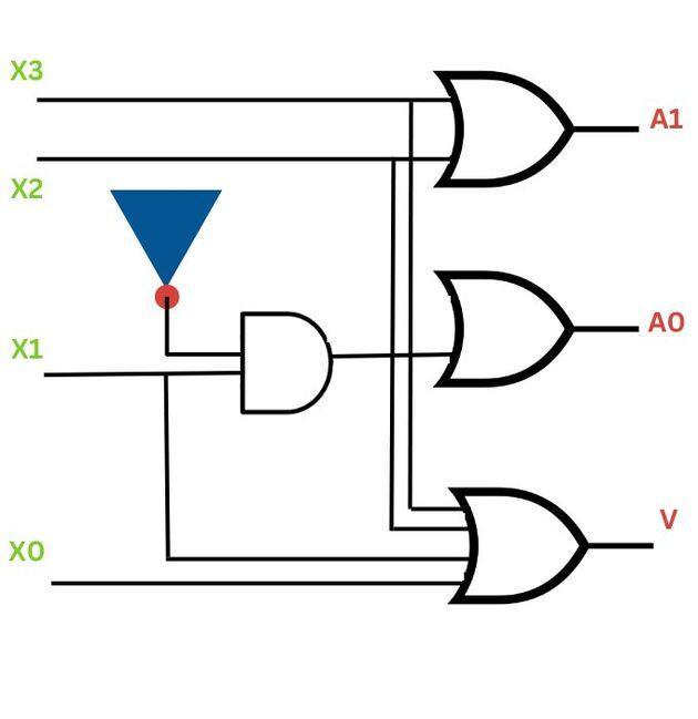
3.4 to 2 line priority encoder
Four inputs and two outputs are in a 4 to 2-line priority encoder (Inputs = X0, X1, X2, and X3, Outputs: A0 and A1). Among the four inputs, X3 has the highest priority, while X0 has the lowest priority. When more than one input is set to 1 at the same time, the result defines the binary code that is linked to the input with the highest priority. Let us understand the working of the priority encoder better with the help of the block diagram and truth table shown below.
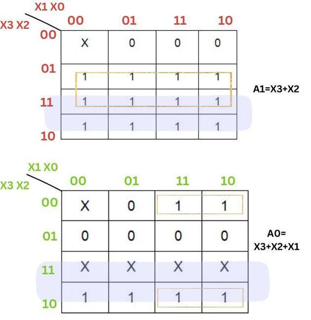
Logical Expression:
A0=X3+X2+X1
A1=X3+X2
Truth Table
Truth Table
Inputs
Outputs
X3
X2
X1
X0
A1
A0
V
0
0
0
0
x
x
0
0
0
0
1
0
1
1
0
0
1
x
0
1
1
0
1
x
x
1
0
1
1
x
x
x
1
1
1
K-map Diagram
Logic Gate Diagram
Uses Of Encoders
The uses of Encoder in Digital Electronics are:
They are used to convert decimals to binary values. This, in turn, helps in performing addition, multiplication, and subtraction in digital systems.
They are used to change analog signals to digital formats. This is used in signal processing.
They are used in detecting interrupts or blocks.
Application of Encoders
Digital Electronics Basics: Focuses on circuits that manage digital signals using binary logic ('0' and '1').
Key Components: Includes capacitors, resistors, multiplexers, counters, transformers, and more.
Encoder in Digital Electronics: A vital component in digital circuits.
Function: Converts a set of binary inputs into a unique binary code.
Purpose of Binary Code: Represents the position of the input, identifying the active specific input.
Application: Widely used in digital systems for converting parallel inputs into a serial code.
Role in Systems: Enhances data processing efficiency and signal transmission.
Advantages of Encoders in Digital Logic
The advantages of Encoder in Digital Electronics are:
Encoders reduce the risk of errors by converting a number of input signals into a single code.
They increase the performance of the digital circuit by increasing the speed of data transfer.
They decrease the lines needed to transfer data from many inputs to a single output.
Disadvantages of Encoders in Digital Logic
The disadvantages of Encoder in Digital Electronics are:
They increase the complexity of the digital system.
They can only be used in cases where there is a conversion of parallel inputs into a serial code.
They can encode a specific number of inputs into a specific number of outputs
What is the most common application of an encoder?
The most common application of an encoder is in motion sensing and control systems, particularly in robotics and industrial automation. Encoders are used to determine the position, velocity, and direction of an object, such as a motor shaft or robotic arm, by converting their motion into a digital signal for precise control and feedback.
Why are encoders more complex than multiplexers?
Encoders accept many input signals and give output as binary code. This requires more logic. Multiplexers select one output from many inputs and process it with simple logic.
What is the difference between an encoder and a decoder?
While encoders are used to convert data into binary code, the decoder accepts binary code to give the original data. Octal to binary encoder is an example of an encoder, while a Binary to Octal encoder is an example of a decoder.
What is the difference between encoding and muxing?
Encoding is the process of converting data into a specific format, often for compression or transmission purposes. Muxing (multiplexing), on the other hand, involves combining multiple signals into a single data stream for easier management or transmission. While encoding changes the format or structure of data, muxing simply combines different data streams without altering their individual formats.
Is encoder analog or digital?
The encoder can be both analog and digital depending on the function and design. Constantly changing analog output signals are produced by analog encoders in response to the position or motion being measured. Using discrete increments or pulses, digital encoders generate a digital output signal that represents the location or motion being monitored.
Conclusion
Encoders are an important device in Digital electronics by transforming a number of inputs in a serial code. The choice of encoders depends on the needs of the digital circuit.
We hope this blog has helped you understand the concept of Encoder in Digital Electronics better. Keep learning! We suggest you read some of our other articles related to digital electronics:
But suppose you are just a beginner and are looking for questions from tech giants like Amazon, Microsoft, Uber, etc. For placement preparations, you must look at the problems, interview experiences, and interview bundles.


 9+ registered

