Table of contents
1.
Introduction 
2.
Encoders
2.1.
4:2 Encoder
2.2.
8:3 Encoder
3.
Decimal to Binary Encoder
4.
Priority encoder
5.
Advantages and Disadvantages of Encoders
5.1.
Advantages
5.2.
Disadvantages
6.
Uses of Encoder
7.
FAQs
8.
Key takeaways
Last Updated: Mar 27, 2024

Encoders

Introduction 

A combinational circuit is a circuit in which we combine the different gates in the circuit. For example: decoder, encoder, multiplexer, and Demultiplexer.

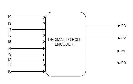
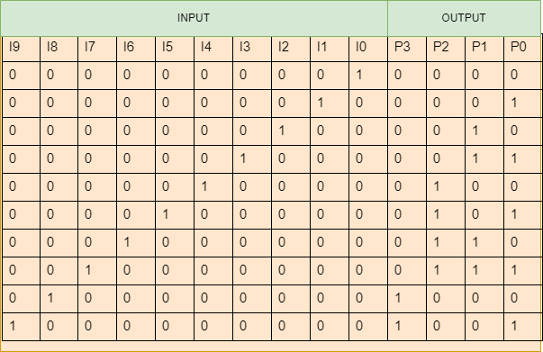
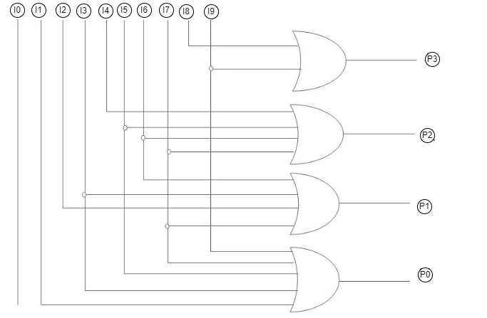
In this article, we will discuss an overview of an encoder which is a combinational circuit that converts binary information in the form of 2^n input lines into n output lines, which represent N bit code for the input.

Read About - Shift Registers in Digital Electronics and Difference Between Jfet and Mosfet

Encoders

These are combinational circuits that perform the opposite operation of Decoders. It can support up to 2^n input lines and 'n' output lines. It will generate a binary code equal to the input, which is active High. As a result, the encoder encodes 2^n input lines using 'n' bits. Encoders may or may not represent the enable signal.

An encoder is either a device, a transducer, or a circuit. The encoder will convert data from one format to another, such as electrical signals to counters or PLCs. The encoder's feedback signal will determine the position, count, speed, and direction. Control devices are used to route commands to specific functions.
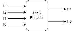
4:2 Encoder

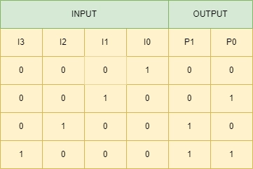
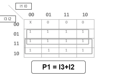
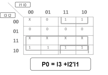
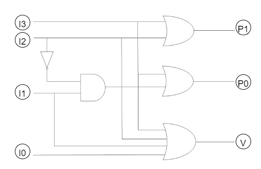
The 4:2 Encoder has four inputs (I3, I2, I1, and I0) and two outputs (P1 and P0). Only one of these four inputs can be '1' at a time to get the corresponding binary code at the output.

The truth table for the 4:2 encoder is as follows:

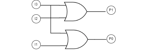
Logical Expression for P1 and P0

  • P1= I3 + I2
  • P0= I3 + I1
     

These two Boolean functions P1 and P0 described above can be implemented using two-input OR gates:
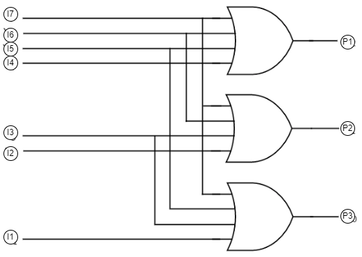
8:3 Encoder

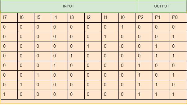
The 8 to 3 Encoder has eight inputs (I7 to I0) and three outputs (P2, P1 and P0). Only one of these eight inputs, which correspond to an octal digit, can be '1' at a time to get the equivalent binary code at the output.

The truth table for the 8:3 encoder is as follows:

Logical Expression for P2, P1 and P0

  • P2 = I7 + I6 + I5 + I4
  • P1 = I7 + I6 + I3 + I2
  • P0 = I7 + I5 + I3 + I1
     

These three Boolean functions P2 P1 and P0 described above can be implemented using three-input OR gates:

Decimal to Binary Encoder

The decimal to binary encoder has 10 input lines and 4 output lines. Each input line corresponds to a decimal digit, and the four output lines correspond to the BCD code. This encoder takes decoded decimal data as input and converts it to BCD output available on the output lines.

The truth table for decimal to the binary encoder is as follows:

Logical Expression for P3, P2, P1 and P0

  • P3= I9+I8
  • P2= I7+I6+I5+I4
  • P1= I7+I6+I3+I2
  • P0= I9+I7+I5+I3+I1


These Boolean functions can be implemented using OR gates:

Priority encoder

The priority encoder is a circuit that compresses many binary inputs into a small number of outputs. The priority encoder's output is a binary representation of the original number of most significant bits. Control interrupt requests are frequently used by acting as the highest priority encoder. We can provide two or more inputs simultaneously, with the highest priority taking precedence.

A 4 to 2 priority encoder has four inputs (I3, I2, I1, and I0) and two outputs (P1 and P0). In this case, input I3 has the highest priority, while input I0 has the lowest. Even if more than one input is '1' simultaneously, the output will be the (binary) code corresponding to the input with higher priority.

The truth table for the Priority encoder is as follows:


These Boolean functions can be implemented using OR gates:


Advantages and Disadvantages of Encoders

Advantages

  • It is highly dependable and precise.
  • It has a higher resolution.
  • Feedback is inexpensive.
  • Its size is small.

Disadvantages

  • When all of the encoder's outputs are equal to zero, there is an ambiguity.
  • If more than one input is active High, the encoder generates an output that may or may not be the correct code.

Uses of Encoder

  • When all of the encoder's outputs are equal to zero, there is an ambiguity.
  • If more than one input is active High, the encoder generates an output that may or may not be the correct code.
  • It is used in automatic health monitoring systems.
  • It is used in CNC machines.

FAQs

  1. What is a binary encoder?
    A binary encoder is a multi-input combinational logic circuit that converts logic level "1" data at its inputs into an equivalent binary code at its output. Depending on the number of data input lines, digital encoders typically generate 2-bit, 3-bit, or 4-bit codes.
     
  2. What is the difference between an encoder and a priority encoder?
    The primary distinction between an encoder and a priority encoder is that the encoder produces an error output when more than one input is high. They are, however, used in data compression applications. As a result, priority encoders are introduced to address the shortcomings of binary encoders.
     
  3. Which gate is known as an equivalence gate?
    EX-NOR gate, the Exclusive OR (XOR) gate's logical complement is the EX-NOR gate, which is a digital logic gate. Because the two-input EX-NOR gate implements logical equality, it is sometimes called an "equivalence gate."

Key takeaways

This article discussed an overview of an encoder and its types and truth table, the boolean functions using different types of gates, and their advantages and disadvantages. 

If you are an absolute beginner, interested in coding, and want to learn DSA, you can look for our guided path for DSA, which is free! 
Thank you for reading!

Live masterclass