Do you think IIT Guwahati certified course can help you in your career?
Introduction
The bits 0 and 1 correspond to the two different ranges of analog voltages. So, during the transmission of binary data from one system to the other, the noise also gets added. Due to this, errors might be there in the received data at the other system.
This means that a bit 0 may change to 1, or a bit 1 may change to 0. It is impossible to avoid noise interference. But, we can definitely get back the original data first by various error detection and correction code techniques.
In this article, we will extensively discuss the need for error detection and correction code techniques and the various techniques like parity code and cyclic redundancy check.
To get back the original data, we first need to detect whether an error is present or not using error detection codes. If the error is present in the code, we will correct it with the help of error correction codes. This is achieved using the following codes:-
Error detection codes
Error correction codes
Error detection codes
Error detection codes detect errors in the received data bitstream. These codes contain some additional bits, which are appended to the original bitstream at the time of transmission. These codes detect the error if it occurs during transmission of the original data bitstream.
Error detecting codes encode the message before sending it over the noisy channels. The encoding scheme is performed so that the decoder at the receiving can easily find the errors in the receiving data with a higher chance of success.
Example: Parity code, Hamming code, etc.
Error correction codes
Error correction codes are used to correct the errors present in the received data bitstream to receive the original data. Error correction codes also use a similar strategy of error detection codes.
Error correction codes are generated using a specific algorithm to remove and detect errors from the message transmitted over the noisy channels. The error-correcting codes find the correct number of corrupted bits and their positions in the message. There are two types of Error Correction Codes (ECCs). They are as follows:-
Block codes In block codes, the message is contained in fixed-size blocks of bits, and the redundant bits are added to correct and detect errors.
Convolutional codes The message consists of data streams of a random length in convolutional codes. And here, the parity symbols are generated by the sliding application of the boolean function to the data stream.
Let's discuss some popular techniques like parity check, cyclic redundancy check, etc.
Parity code
In the parity code, we add one parity bit either to the left to the MSB(Most Significant Bit) or the right of the LSB(Least Significant Bit) to the original bitstream. Based on the parity type being chosen, there are two types of parity codes: even parity codes and odd parity codes.
Even Parity Codes
In an even parity code, there are an even number of ones present. It contains the data bits as well as an even parity bit. The value of the even parity bit should be zero if an even number of ones are present in the binary code. Otherwise, the even parity bit should be one.
The table shows the even parity codes corresponding to each of the 3-bit binary codes.
Binary Code
Even Parity bit
Even Parity Code
000
0
0000
001
1
0011
010
1
0101
011
0
0110
100
1
1001
101
0
1010
110
0
1100
111
1
1111
Note: The even parity bit is included to the right of the LSB of binary code.
4 bits are present in the even parity codes. The parity codes can have 0, 2, or 4 ones to have an even parity code.
If the receiver system receives one of the even parity codes, no error is there in the received data. The bits other than even parity bit are the same as that of binary code.
If the receiver system receives a code other than an even parity code, the received data will have an error. However, the original binary code cannot be obtained as we are unaware of the bit position of the error.
Odd Parity Codes
There is an odd number of ones present in an odd parity code. It contains the data bits as well as an even parity bit. The value of the odd parity bit should be one if an even number of ones are present in the binary code. Otherwise, the odd parity bit should be zero.
The table shows the odd parity codes corresponding to each of the 3-bit binary codes.
Binary Code
Odd Parity bit
Odd Parity Code
000
1
0001
001
0
0010
010
0
0100
011
1
0111
100
0
1000
101
1
1011
110
1
1101
111
0
1110
Note: The even parity bit is included to the right of the LSB of binary code.
4 bits are present in the odd parity codes. The parity codes can have 1 or 3 ones to have an odd parity code.
If the receiver system receives one of the odd parity codes, there is no error in the received data. The bits other than the odd parity bit are the same as that of binary code.
If the receiver system receives a code other than an odd parity code, the received data will have an error. However, the original binary code cannot be obtained as we are unaware of the bit position of the error.
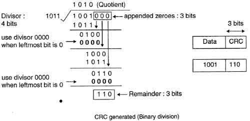
Cyclic Redundancy Check (CRC) is an error detection mechanism in which a unique number is appended to a data block to detect any errors introduced during storage or transmission). The unique number is recalculated on retrieval and compared to the value originally transmitted, revealing certain error types.
CRC is given as a k bit message, and the transmitter creates an (n – k) bit sequence called a frame check sequence. The outcoming frame, including n bits, is precisely divisible by a fixed number. Modulo 2 Arithmetic is used in this binary addition with no carries, similar to the XOR operation. The redundancy bits used by CRC are changed by splitting the data block by a fixed divisor.
Procedure
A string of 'n' 0s is added to the data block. 'n' is one smaller than the number of bits in the divisor.
Using a binary division procedure, the new data block is divided by a divisor. The remainder obtained from the division is the CRC.
The CRC of 'n' bits interpreted in step 2 restores the added 0s at the end of the data block.
Step 2: During this division process, whenever the leftmost bit of dividend or remainder is 0, we use a string of 0s of the same length as the divisor. Thus, in this case, the divisor 1011 is replaced by 0000.
Step 3: At the receiver side, the data received is 1001110.
Step 4: This data is again divided by a divisor 1011.
Step 5: The remainder obtained is 000. This implies there is no error.
What is an error in data transmission? An error is when the receiver's information does not match the sender's information. During the transmission, digital signals may suffer from noise that can introduce errors in the binary bits(0/1) traveling from the sender end to the receiver end.
Mention some of the features of error detection codes. Some of the features of error detection codes are as follows:- Error detection codes are used when we use message backward error correction techniques for reliable data transmission. The receiver sends a feedback message to inform the sender whether the message is received without any error or not at the receiver side. If the message contains errors, the sender retransmits the message. The message is contained in fixed-size blocks of bits in error detection codes. In this, the redundant bits are added for correcting and detecting errors. Error detection codes involve checking the error.
Explain the two-dimensional parity check. In a two-dimensional parity check, the parity check bits are calculated for each row, like a normal parity check bit. The parity check bits are also calculated for all columns, and then both are sent along with the data. These are compared with the parity bits calculated on the received data at the receiving end.
What are the qualities required for CRC? The qualities required for CRC are as follows:- CRC must have accurately one less bit than the divisor. Adding the CRC to the end of the data block should result in the bit sequence that is divisible by the divisor.
Key Takeaways
In this article, we have extensively discussed the need for error detection and correction code techniques and the various techniques like parity code and cyclic redundancy check. Error detection and correction code play an essential role in transmitting data from one source to another. And it is vital to have proper knowledge of this to avoid receiving erroneous data.
We hope that this blog has helped you enhance your knowledge regarding error detection and correction code techniques and if you would like to learn more, check out our articles on Error Detection and Correction Code: Part 2. Do upvote our blog to help other ninjas grow. Happy Coding!


 8+ registered

