Terminologies used in IF Metrics
- Component: The parts or constituents of a decomposed (software) system are called components.
- Cohesion: A measure of the degree to which a component performs a single function is called cohesion. If a component does numerous discrete tasks, it lacks cohesion.
-
Coupling: The degree of linkage between one component to others in the same system is called coupling. A highly coupled component is linked to many components, whereas a slightly coupled component is linked to only a few.
Also read V Model in Software Engineering
Information Flow Model
Information Flow metrics measure the information flowing among modules of the system. It is responsive to the complexity due to interconnection among system components. This measure also includes the complexity of a software module, which is the sum of all the complexities of the methods present in the module. A procedure contributes complexity due to the following two factors.
- The complexity of the process code itself.
-
The complexity due to the process's linkage to other processes. The effect of the first case has been included through the LOC (Line Of Code) measure. For estimating the second case, Henry and Kafura have described two terminologies: FAN IN and FAN OUT.
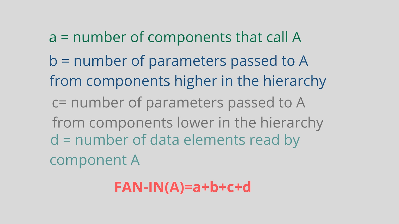
FAN-IN: FAN-IN of a component is a count of the number of other components that can call or pass information to that component.
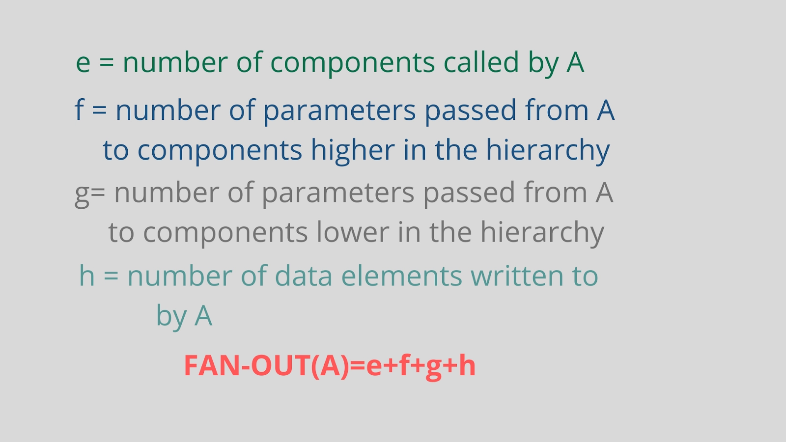
FAN -OUT: FAN-OUT of a component is the number of components that are called by or receive information from that component.
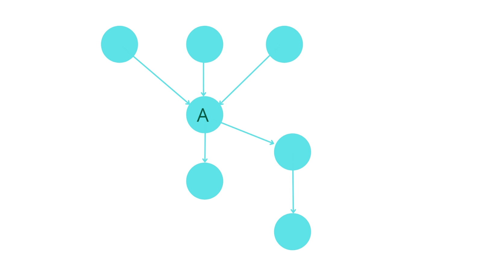
The figure given below shows a fragment of a system design having component 'A,' for which we can define three measures:
- ‘FAN-IN’ is a count of the number of other components calling or passing control to A.
- ‘FAN-OUT’ is the number of components called by A.

Figure: Aspects of complexity
3. The information flow index of component A, abbreviated as IF(A), is derived from the first two components by using the following formula-
IF(A) = [ FAN-IN(A) * FAN-OUT(A) ]2


Steps to derive the most simple IF Metrics.
- First, note each component's level in the system model.
- Calculate the number of calls, i.e., FAN-IN of each component. Components at the top-most level should have a FAN-IN of zero. More than one component in the design is allowed to be at the top-most level in some organisations, so for them, FAN-IN of one is taken. Also, a simple model of FAN-IN can penalise reused components.
- For each component, count the number of calls from the component. For a component that calls no other, assign a FAN OUT value of one.
- Evaluate the IF value for each component using the above formula.
- Add the IF value for all components within each level. This is called the level sum.
- Add the IF values for the total system design. This is called the system sum.
- Rank the component according to FAN IN, FAN OUT, and IF values for each level. Prepare three histograms or lines for each level.
- The level sum values for each level should be plotted using a histogram or line plot.
Conclusion
- Components having a lack of cohesion and high linkage (highly coupled) are less reliable and difficult to maintain.
- High FAN-IN values of a component indicate that they lack cohesion. It also suggests that the functions are not broken down to a significant enough degree. These components are often called because they are doing more than one job.
- High levels of FAN-OUT also indicate a lack of cohesion or missed levels of abstraction. Generally, FAN-OUT appears to be a better indicator of problem modules than FAN-IN.
- High IF values indicate highly coupled components.
FAQs
-
Consider the following system. Calculate FAN-IN and FAN-OUT of A, and what do they indicate?

FAN-IN(A) = 3, FAN-OUT(A) = 2
1. High FAN-IN indicates this module has been used heavily. This shows the reusability of modules and thus reduces redundancy in the coding.
2. High FAN-OUT indicates a highly coupled module, thus more dependency on other modules.
-
How do FAN-IN and FAN-OUT of a module affect the design structure?
Higher FAN-IN means heavy use of that module, i.e., the module's reusability and better design structure. In contrast, high FAN-OUT means highly coupled,i.e., more dependent on others, showing poor design structure and high maintainability cost.
-
Define the terms cohesion and coupling.
Cohesion: A measure of the degree to which a component performs a single function is called cohesion.
Coupling: The degree of linkage between one component to others in the same system is called coupling.
Key Takeaways
In this article, we have extensively discussed Information Flow Metrics, terminologies associated with them and their implementation, and some questions related to this topic. We hope that this blog has helped you enhance your knowledge and if you wish to learn more, check out our Coding Ninjas Blog site and visit our Library. Do upvote our blog to help other ninjas grow.
Check out this problem - Largest Rectangle in Histogram
Happy Learning!


