Do you think IIT Guwahati certified course can help you in your career?
Introduction
This blog will learn about Inter-integrated circuits, how to work, and their advantages and disadvantages. It is also known as TWI (Two Wired Interface). I squared C, frequently called I2C, stands for the Inter-Integrated Circuit protocol. I2C was invented in 1982 with the aid of Philips Semiconductor, now called NXP. If you know about I2C, it is a good thing; if you do not know, then it is even better; this blog is only and only for you; let’s start.
I2C Communication Protocol
I2C stands for Inter-Integrated Circuit and bus interface connection protocol incorporated into devices for serial communication. Philips Semiconductor initially designed it in 1982. Recently it has been a widely used protocol for short-distance transmission.
It is extensively followed for communication among microcontrollers and sensor arrays, displays, IoT devices, EEPROMs etc.
This is a sort of synchronous serial communication protocol. Data bits are transferred at normal periods set by a reference clock line.
Features
Only two comm standard lines (wires) are required to control any device/IC on the I2C network.
There is no need for prior settlement on the data transfer rate like in UART communication. So the data switch pace can be adjusted every time required.
Simple mechanism for validation of data transferred.
It uses a 7-bit addressing machine to target a particular device/IC at the I2C bus.
I2C networks are easy to scale. New devices can, without a doubt, be connected to the two widespread I2C bus traces.
According to I2C protocols, the information line can not change when the clock; is excessive. It can trade only when the clock line is low. The two lines are open drains; hence, a pull-up resistor is required to keep the lines excessive for devices on the I2C bus that are active low. The statistics are transmitted in the form of packets which incorporate nine bits. The sequence of these bits is –
Start Condition – 1 bit
Slave Address – 8 bit
Acknowledge – 1 bit
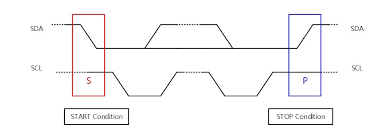
Start and Stop Conditions
START and STOP may be generated via preserving the SCL line high and changing the level of SDA. The SDA is changed from excessive to low to develop the START condition while maintaining the SCL high. To generate the STOP condition, SDA goes from low to high while keeping the SCL high, as shown in the figure below.
Between each start and stop circumstance pair, the bus is considered as busy, and no master can take manage of the bus. If the master tries to start a new transfer and no longer wants to release the bus earlier than beginning the new transfer, it troubles a unique START situation. It is called a REPEATED START situation.
Read/Write Bit
An excessive Read/Write bit indicates that the master is sending the data to the slave, whereas a low Read/Write bit means that the master is receiving records of information from the slave.
ACK/NACK Bit
After every data frame goes along with an ACK/NACK bit, if the data frame is obtained successfully, the ACK bit is despatched to the sender.
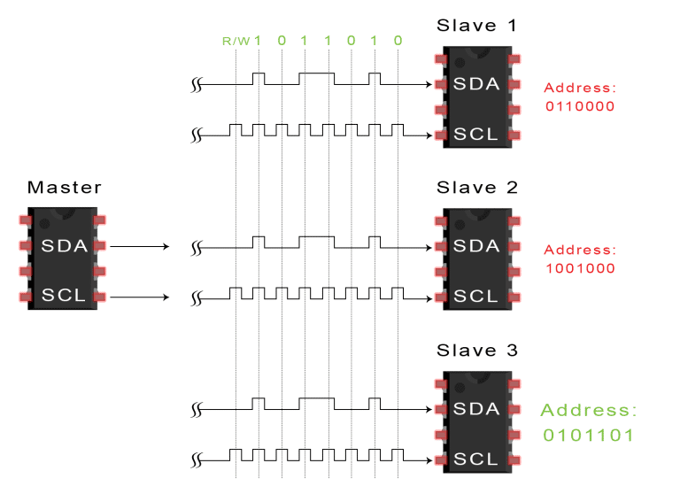
Addressing
The address frame is the primary frame after the beginning bit. The deal with the slave with which the master sends the master desire to communicate to every slave connected with it. The slave then compares its address with this address and sends ACK.
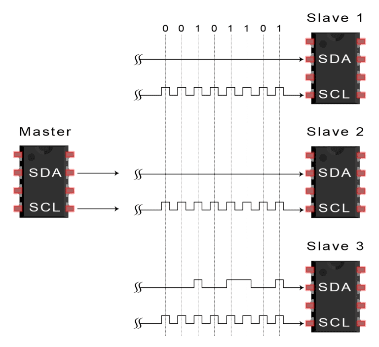
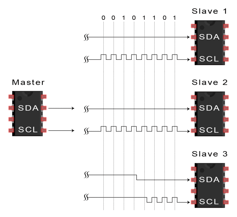
I2C Packet Format
In the I2C communique protocol, the records are transmitted in packets. These packets are 9 bits lengthy, out of which the first 8 bits are positioned in the SDA line, and the 9th bit is reserved for ACK/NACK, i.e. Acknowledge or Not Acknowledge by using the receiver.
“START condition plus address packet plus multiple data packets plus STOP condition together form an entire Data switch”.
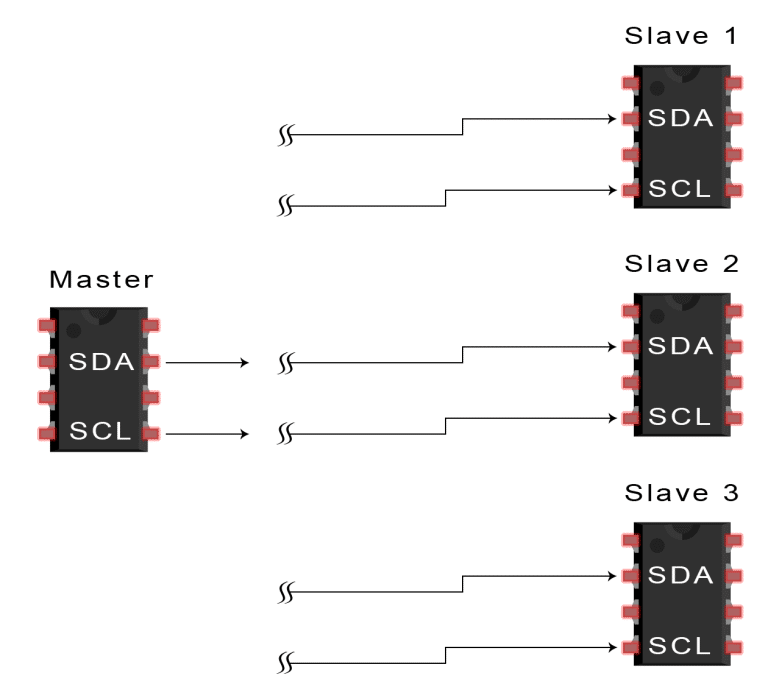
Data Transmission In I2C
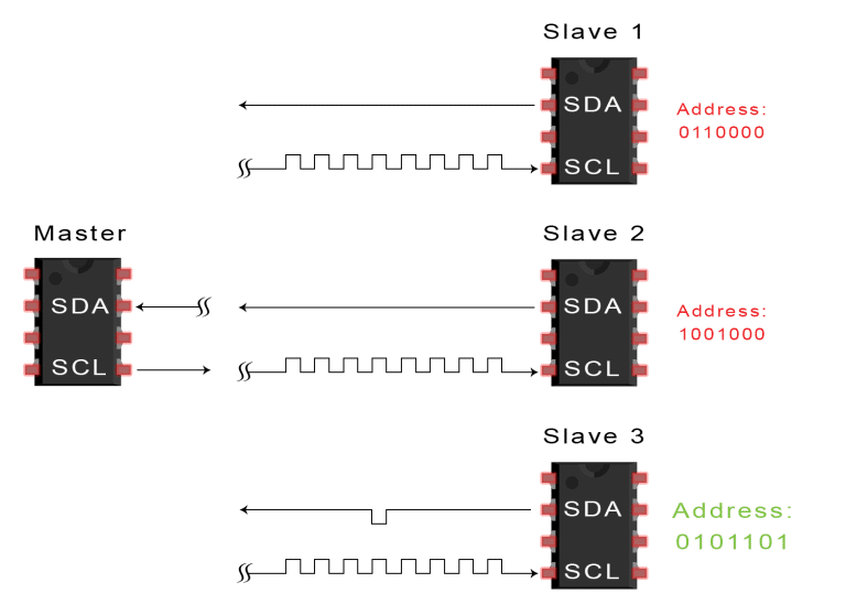
The master sends the start circumstances to each related slave via diverting the SDA line from a high voltage level to a low voltage level earlier than switching the SCL line from high to low:
Each slave compares the address get off from the master to its address. If the address coordinate with, the slave returns an ACK bit with the aid of pulling the SDA line low for one bit. If the lesson from the master does not match the slave’s address, the slave leaves the SDA line excessive.
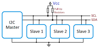
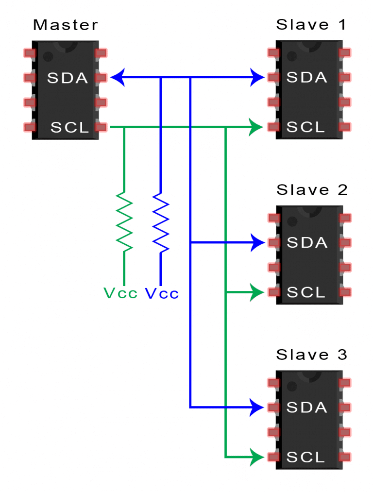
Because I2C uses addressing, more than one slave can be curbed by a single master. With a 7 bit address, 128 (27) precise addresses are available. Using 10-bit addresses is uncommon but offers 1,024 (210) individual lessons. To join more than one slaves to a single master, wire them like this, with 4.7K Ohm pull-up resistors connecting the SDA and SCL lines to Vcc:
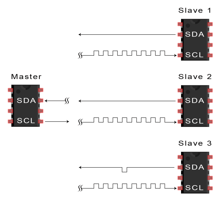
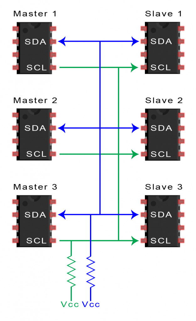
Multiple masters can be related to a single slave or numerous slaves. The hassle with more than one master inside the same device comes while masters attempt to send or receive facts concurrently over the SDA line. Each master desires to detect if the SDA line is low or excessive before transmitting a message to solve this problem. If the SDA line is down, another master has control of the bus, and the master should wait to send the message. If the SDA line is high, transmitting the statement is safe. To connect a couple of masters to a couple of slaves, use the following diagram, with 4.7K Ohm pull-up resistors joining the SDA and SCL lines to Vcc:
Complexity is reduced because it uses only two bi-directional lines (unlike SPI Communication).
Cost-efficient.
It uses ACK/NACK attribute, due to which it has enhanced error handling capabilities.
Disadvantages
Slower data transfer rate than SPI
The size of the data frame is limited to 8 bits.
More intricated hardware needed to implement than SPI
Frequently Asked Questions
What limits I2C speed?
Speed is one factor that restricts the I2C bus application; a pull-up resistor that sets a logic determines the bus's maximum transfer speed, so the high-speed mode at a 3.4 Mbit/s is introduced.
How do you check I2C lines?
You can begin the testing process by verifying each of the following functions on the I2C bus: START and STOP condition technology. A start condition is generated whilst the serial data (SDA) line switches from high to low voltage, and the serial clock (SCL) line switches from high to low.
Can I2C have multiple masters?
The I2C component is an ideal solution when networking multiple devices on a single board or undersized system. The system can be designed with a single master and multiple slaves, multiple masters, or a combination of masters and slaves.
Conclusion
This blog has extensively discussed I2C topics and their implementation in Arduino software/tools. This article also explains the working of I2C to view and Data transmission in I2C.
We hope that this blog has helped you enhance your knowledge regarding I2C and if you would like to learn more, check out our articles on reading books and much more.


 9+ registered

