Do you think IIT Guwahati certified course can help you in your career?
Introduction
A Digital logic circuit has voltage levels that are to be switched from one value to another but have a finite number of distinct values. These circuits have a definite set of logic rules, so they are also known as Logic circuits. There are mainly two types of digital logic circuits, namely:
Combinational Logic Circuits
Sequential Logic Circuits
Digital logic circuits are also known as switching circuits. These circuits are commonly used in most digital electronic devices such as computers, calculators, mobile phones, etc.
In this blog, we will discuss the combinational circuits in detail. We have already covered the sequential circuits in another blog. Refer to both the blogs to get a good grasp on digital circuits.
What are Combinational Circuits?
A combinational circuit consists of logic gates whose outputs are determined from the present combination of inputs and they have no memory. These circuits are developed using OR, AND, NOT, NAND, and NOR logic gates. These logic gates are the building blocks of combinational circuits. A combinational circuit consists of input and output variables. These circuits are independent of the previous input to generate an output. A combinational circuit can have an ‘n’ number of inputs and ‘m’ number of outputs. The output in these circuits at any time is a direct function of the applied external inputs.
Common combinational circuits constructed using single logic gates that carry out the desired application include Encoders, Decoders, Multiplexers, De-multiplexers, Full and Half Adders, etc.
Representation of Combinational Circuits
Logic Gates: The logic gates are used to perform the basic logical functions which are necessary for digital circuits. Logic gates are today extensively used in digital circuits. The decision is made in a logic gate based on the combination of the input digital signals in the logic gates. These are the building blocks in the construction of combinational logic circuits. Commonly NAND, NOT, NOR, OR, AND logic gates are used for the construction.
Boolean Algebra : It is the branch of algebra that deals with only true and false values. It is used in digital circuits to make logical decisions. It helps to analyze and simplify the digital circuit and logic gates and the boolean expressions involved in them. It is one of the main approaches used to represent a combinational logic circuit.
Truth Table: The truth table described for a digital circuit logic system describes how the output and input for the given circuit are related. It has defined input and output labels that correspond to the given input and the produced output for a logic system. This method calculates the operational values of the logical expressions for every combination of values taken by their logical variables. All the output columns are represented in a single table.
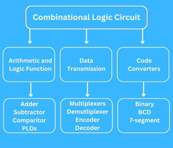
Classification of Combinational Circuits
The combination circuits are further classified into three categories:
Arithmetic and Logic Functions
The Arithmetic and Logic Functions are some of the fundamental operations that are used in digital electronics. These operations are performed on binary data. The operation used can be enabled to improve the computation and helps in performing logical and comparative operations efficiently.
The operations performed on the binary data include arithmetic and logical operations. These operations are used to further design adders, subtractors, comparitors, and PLDs. Basic arithmetic operations include addition, subtraction, multiplication, and division. Basic logic operations include AND, OR, and NOT.
Data Transmission
Data transmission in digital electronics involves sending data using various methods and protocols. The entered data by the user is generally converted before being transmitted to ensure the transmission occurs without any delay and loss of data. Also, it is used to ensure data security and maintains the integrity of data.
The entered data by the user is encoded by the electronics in the keyboard into an equivalent binary coded pattern using one of the standard coding schemes used for interchanging information. Devices commonly used for data transmission are Multiplexers, Demultiplexer, Encoders, Decoders.
Code Converters
Code Converters are used to get a required code from one type of given code. The combinational circuits can be used to perform code conversion. There are different types of binary codes like BCD code, gray code, excess-3 code, etc. Depending on the use case the type of code converter can be used.
A code converter circuit converts the binary information from one form to another. There are various binary forms, including BCD, 7-segment, etc.
Types of Combinational Circuits
There are mainly three types of combinational circuits that are used extensively. The following are the three types of combinational circuits.
1. Half Adder
Half adders are combinational circuits that give the binary sum of two single-bit binary numbers. It has two inputs and two outputs. The two inputs are the regular ones. One output is the regular one(LSB) and the other one is the carry output(MSB). It can be used to implement basic gates like AND and XOR.
2. Full Adder
Full adders are combinational circuits that take three inputs and give two outputs. The inputs are two regular inputs(A and B) and one carry input(Cin). The outputs are one sum output(S) and one carry output(Cout). The output carry is also called the majority 1s detector, which is high if more than one input is high. The logical expression for the sum is Cin xor (A xor B) and for the carry output is AB + BCin + ACin.
3. Half Subtractors
Half subtractors are combinational circuits that give the binary subtraction of two single-bit binary numbers. It has two inputs and two outputs. The two inputs are the regular ones. One output is the difference between the two inputs, and the other denotes whether borrowing was done. It can be used to implement basic gates like XOR and NOT.
4. Full Subtractors
Full subtractors are combinational circuits that give the binary subtraction of two bits. It takes three inputs: minuend(A), subtrahend(B), and the previous borrow bit(Bin). It has two outputs representing the difference(D) and the output borrow(Bout). The logical expression for the difference is (A xor B) xor Bin and for the output borrow is A'Bin + A'B + BBin.
5. Decoders
Decoders are combinational circuits that are used to convert a given binary code so that it can be interpreted by a human. For example, we can have a decoder with a given input as an eight-bit binary number that will convert it to a seven-segment display.
6. Encoders
Encoders are combinational circuits that convert a set of input signals into a coded output representation. Encoders are widely used to encode information for many reasons. For Example, we might have a 4 to 2 binary encoder that is used to convert four input lines and produce a 2-bit binary code output.
7. Multiplexers
Multiplexers are combinational circuits that are used to take several inputs from the user and select the desired output to be passed from it. Multiplexers are used in many electronic devices such as computer memory chips and data communication devices.
8. Demultiplexers
Demultiplexers are combinational circuits that take a single input and choose one of the multiple output lines as the output signal. It is the opposite of the multiplexer. It has selectors helping in the decision for the desired output.
Features of Combinational Circuits
The output is dependent only on the present input.
These circuits are faster and time-independent.
These circuits are easy to design.
There is no feedback between input and output which helps in reducing the complexity.
Logic gates are the building blocks of combinational circuits.
These circuits are used in arithmetic and Boolean operations.
They don’t have any storage feature, unlike sequential circuits.
Applications of Combinational Circuits
Combinational circuits are electric circuits where the output is dependent on the present combination of inputs. Combinational circuits find their application in digital electronics as computers, chips, and microprocessors to perform operations on data. The following are some of the major applications of combinational circuits.
We can use combinational circuits to implement various arithmetic operations. The most commonly used arithmetic operations are addition, subtraction, multiplication, and division.
We can use combinational circuits to implement logic gates that are used for performing various logical operations. The logical operations implemented are AND, OR, NOT, NOR, etc.
We can use combinational circuits to implement the multiplexer. The multiplexers are used to take several inputs from the user and select the desired output to be passed from it. Multiplexers are used in many electronic devices such as computer memory chips and data communication devices.
The combinational circuits can be used to implement a full adder, which is a logic gate that takes two binary digits as input and gives the result as a sum and a carry bit. The full adders can be used in electronic devices such as computers and calculators.
Difference between Combinational and Sequential Circuits
There are some significant differences between the combinational and sequential circuits:
S.No
Combinational Circuit
Sequential Circuit
1.
This type of circuit in which the output is independent of time and relies on the input present at that instant.
This is the type of circuit where the output relies on the current and previous outputs.
2.
They are faster and better in performance.
They are slower and have low performance.
3.
No implementation of feedback makes these circuits less complex.
Implementation of feedback makes these circuits more complex.
4.
Elementary building blocks are logic gates.
Elementary building blocks are flip-flops.
5.
These are mainly used for Arithmetic and boolean operations.
They are mainly used for storing data.
Frequently Asked Questions
What is combinational circuit with example?
Combinational circuits are the components of digital electronics that are used to perform various operations on data. For example, multiplexers are used to take several inputs from the user and select the desired output to be passed from it.
What are the 4 combinational circuits?
The major four combinational circuits are half adders, full adders, multiplexers, demultiplexers, encoders, and decoders. All of the above-mentioned combinational circuits are used to perform various operations on data in digital circuits making the circuits more robust.
What are sequential and combinational circuits?
Sequential circuits are the ones that depend on the clock cycles and are dependent on the present as well as past inputs to generate the final output. Combinational circuits are time-independent circuits that are independent of the past inputs to generate the output.
Conclusion
This blog discussed combinational logic circuits and their types. We also discussed some common features and classification in combinational logic circuits.


 9+ registered

