Table of contents
1.
Introduction
2.
Asynchronous Counter 
2.1.
Operation for Asynchronous Counter
3.
Synchronous Counter
3.1.
Operation for Synchronous Counter
4.
Decade Counter
5.
Classification of Counters
5.1.
UP/DOWN Counter
5.2.
UP/DOWN Ripple Counters
6.
Modulus Counter (MOD-N Counter)
7.
FAQs
8.
Key Takeaways
Last Updated: Mar 27, 2024

Introduction to Counters

Career growth poll
Do you think IIT Guwahati certified course can help you in your career?

Introduction

A counter is a unique type of sequential circuit or device used to store the number of times a specific event or procedure has occurred, frequently about a clock signal. We use counters in digital electronics to count how many times a particular event happened in the circuit. For example, the UP counter increases the count for every rising edge of the clock. We can also design counters with the help of flip-flops. Not only can a counter count, but it can also follow a specific sequence depending on our design, such as any random sequence 0,1,3,2...

We have two types of category of counters -

  • Asynchronous/Ripple counters
  • Synchronous counters

Asynchronous Counter 

The asynchronous counter is also called the ripple counter. We use two T flip flops or J K flip flops by setting both of the inputs to 1 permanently. In an asynchronous counter, there is no universal clock. The clock drives only the first flip flop of the asynchronous counter, and the rest are driven by the output of the previous flip flop. We will understand this with the help of the following diagram-

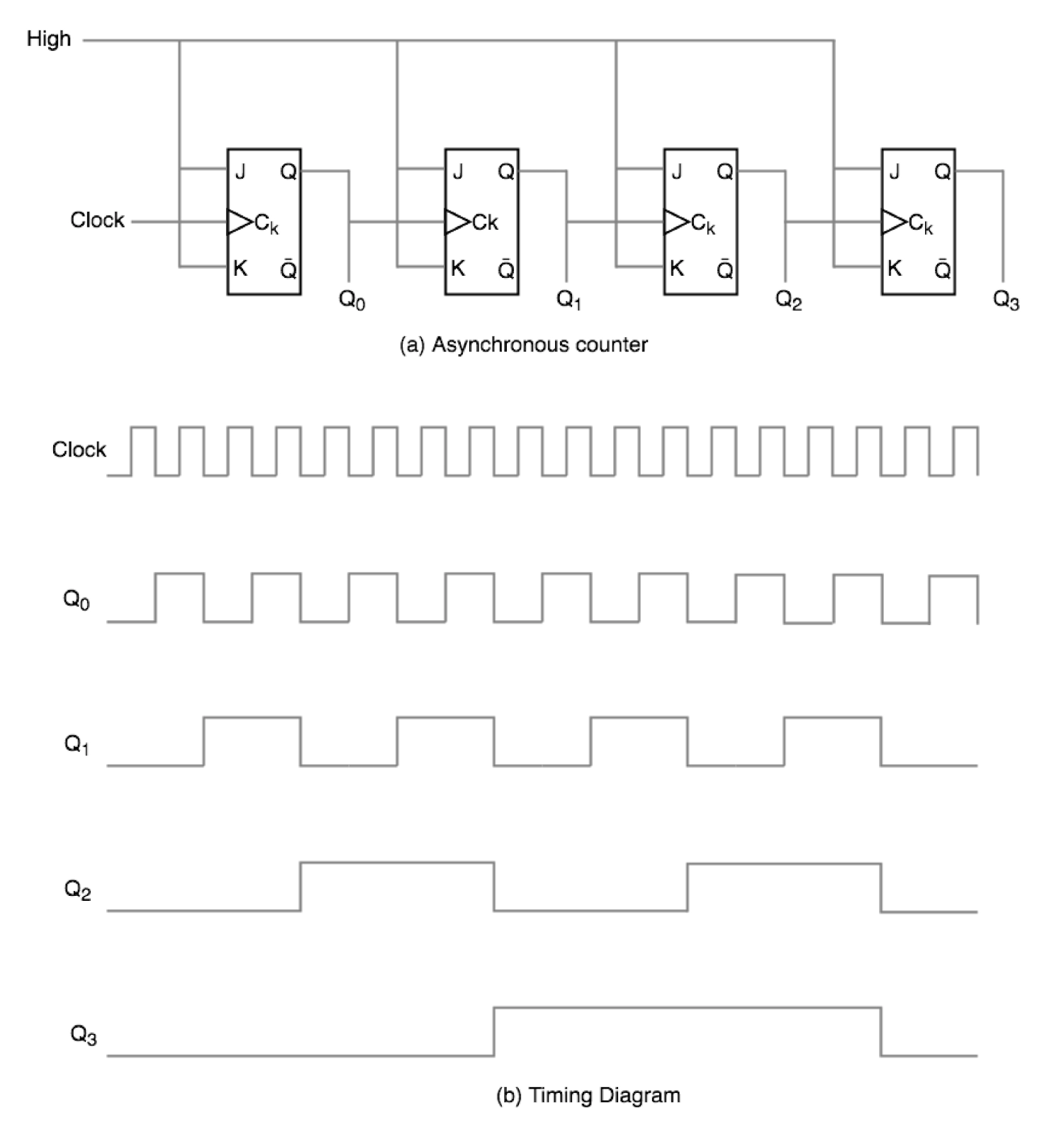
As seen in the timing diagram, as soon as the clock pulse rising edge is encountered, Q0 changes. Furthermore, when the rising edge of Q0 is encountered, Q1 changes because Q0 is the clock pulse for Q1. Because ripples are created in this manner by Q0, Q1, Q2, Q3, it is also known as the RIPPLE counter.

Operation for Asynchronous Counter

For now, we will see the operation for only two flip flips with output Q0 Q1.

Condition 1: Both flip flops are in rest condition.

Operation: The output of both the flip flops will be 0. 

Condition 2: While the first negative clock edge occurs.

Operation: The output of the first flop will change from 0 to 1 as it will toggle. Then the clock input of the next flip flop will take the output of the first flip flop. Because it is the negative edge-triggered flip flop, this input does not affect the output state of the second flip flop.

Condition 3: During the occurrence of the second negative clock edge.

Operation: Now, the first flip will toggle again, and its output will change from 1 to 0. The second flip flop will use this output as a negative edge clock. Because it is the negative edge-triggered flip flop, this input will affect the output state of the second flip flop.

Condition 4: During the occurrence of third negative clock edge.

Operation: Now, the first flip will toggle again, and its output will change from 0 to 1. The second flip flop will use this output as a positive edge clock. Because it is the negative edge-triggered flip flop, this input will not affect the output state of the second flip flop.

Condition 5: During the occurrence of the fourth negative clock edge.

Operation: Now, the first flip will toggle again, and its output will change from 1 to 0. The second flip flop will use this output as a negative edge clock. Because it is the negative edge-triggered flip flop, this input will affect the output state of the second flip flop.

Synchronous Counter

The synchronous counter has a global clock connected to every flip flop and drives them so that its output changes parallelly. The one benefit of synchronous counters over asynchronous counters is that they may run at greater frequencies than asynchronous counters since they do not have a cumulative delay because each flip flop is given the same clock.

According to the circuit schematic, Q0 bit responds to each falling edge of the clock, Q1 is dependent on Q0, Q2 is dependent on Q1 and Q0, and Q3 is dependent on Q2, Q1, and Q0.

Operation for Synchronous Counter

For now, we will see the operation for only two flip flips with output Q0 Q1.

Condition 1: Both flip flops are in rest condition.

Operation: The output of both the flip flops will be 0. 

Condition 2: While the first negative clock edge occurs.

Operation: The output of the first flop will change from 0 to 1 as it will toggle. When the first negative clock edge occurs, the first flip flop's output will be 0. The first flip flop's clock input and both of its inputs will be set to 0. The condition of the second flip flop will remain unchanged in this manner.

Condition 3: While the second negative clock edge occurs

Operation: Now, the first flip will toggle again, and its output will change from 1 to 0. When the first negative clock edge occurs, the first flip flop's output will be 1. The first flip flop's clock input and both of its inputs will be set to 1. The condition of the second flip flop will change to 1 in this manner.

Condition 4:While the third negative clock edge occurs

Operation: Now, the first flip will toggle again, and its output will change from 0 to 1. However, in this case, both the inputs and the clock input are set to 0. As a result, the outputs will stay unchanged.

Condition 5: While the fourth negative clock edge occurs

Operation: Now, the first flip will toggle again, and its output will change from 1 to 0. In this case, the second flip flop and clock input are set to 1. As a result, the outputs will change from 1 to 0.

Decade Counter

A decade counter counts ten distinct states before returning to its starting values. A basic decade counter counts from 0 to 9, but we can also create decade counters that can cycle through any ten states from 0 to 15(for 4 bit counter).

Truth Table

Clock Pulse 

Q3

Q2

Q1

Q0

0

0

0

0

0

1

0

0

0

1

2

0

0

1

0

3

0

0

1

1

4

0

1

0

0

5

0

1

0

1

6

0

1

1

0

7

0

1

1

1

8

1

0

0

0

9

1

0

0

1

10

0

0

0

0

Circuit Diagram

The circuit diagram shows that we used a NAND gate for Q3 and Q1 and sent this to the clear input line since the binary representation of 10 is- 1010

And we can see that Q3 and Q1 are both ones here; if we feed the NAND of these two bits to the clear input, the counter will be cleared at ten and will restart from the beginning.

Note: The number of flip flops used in a counter is always larger than (log2 N), where N is the number of states.

Classification of Counters

Depending on how the counting proceeds, synchronous or asynchronous counters are classed as follows:

  • Up counters
  • Down counters
  • Up/Down counters

UP/DOWN Counter

A UP/DOWN counter is created by combining an UP counter with a DOWN counter. There is also a mode control (M) input to select between UP or DOWN modes. To perform the UP/DOWN function, a combinational circuit must be built and employed between each pair of flip-flops.

Types of Up/down counters-

  • UP/DOWN ripple counter
  • UP/DOWN synchronous counter

UP/DOWN Ripple Counters

All flip-flops are operated in toggle mode in the UP/DOWN ripple counter. We use either JK flip flop or T flip flop. The LSB flip flop is driven by the clock directly, and the rest of the flip flop gets clock input or output of the previous flip flop.

  • UP counting mode (M=0)

If UP counting is desired, the Q output of the previous FF is linked to the clock of the following stage. The mode chosen input M is set to logic 0 (M=0) for this mode.

  • DOWN counting mode (M=1)

Suppose M = 1, then the previous FF's Q bar output is linked to the following FF. This will activate the counter's counting mode.

Modulus Counter (MOD-N Counter)

The 2-bit ripple counter is the MOD-4 counter, while the 3-bit ripple counter is the MOD-8 counter. As a result, an n-bit ripple counter is a modulo-N counter. In this case, MOD number = 2n.

Must Read Shift Registers in Digital Electronics

FAQs

  1. What are the types of Modulus counters?
    The types of Modulus counters are:-
    2-bit up or down (MOD-4)
    3-bit up or down (MOD-8)
    4-bit up or down (MOD-16)
     
  2. What are the applications of counters? 
    Frequency counters
    Digital clock
    Time measurement
    Frequency divider circuits
    Digital triangular wave generator.
    A to D converter
     
  3. How many flip-flops are needed to construct a MOD-32 binary counter?
    An n-bit ripple counter is a modulo-N counter. So, we need five flip-flops.
     
  4. What is the difference between combinational logic and sequential logic?
    Timing pulses do not trigger Combinational circuits, but timing pulses trigger sequential circuits.
     
  5. If a 6 bit counter is used to count from 0,1,2,3.....n, what is the value of N?
    There are 2N states in N bit counter and can count from 0 to 2N -1. So, here N = 63.

Key Takeaways

In this blog, we learned about Counters. We discussed its different types and operations. Don't come to a halt here. Check out our Counters in Digital LogicMap and Map simplification. You can also check out the AdderSubtractor and Master-Slave Flip Flop blogs. Check out for more blogs here.

Source - Giphy 

Happy Learning!

Live masterclass