Table of contents
1.
Introduction
2.
What is a JK flip flop?
2.1.
JK flip-flop Truth table 
3.
Master-Slave JK Flip-flop
3.1.
Characteristic Table:
4.
 
5.
 
6.
 
7.
 
8.
 
9.
Applications of JK Flip-Flop
10.
Advantages of JK Flip-Flop
11.
Disadvantages of JK Flip-Flop
12.
Frequently Asked Questions
12.1.
What is a clock in a flip flop?
12.2.
What is the status of Q output when J= 1 and k= 0?
12.3.
How is a J-K flip-flop made to toggle? 
12.4.
What is the toggle condition?
12.5.
What is J in JK flip-flop?
13.
Conclusion
Last Updated: Mar 30, 2025
Easy

JK flip flop - Diagram, Full Form, Tables, Equation

Author Aryan Raj
0 upvote
Career growth poll
Do you think IIT Guwahati certified course can help you in your career?

Introduction

A JK flip-flop is a sequential bi-state single-bit memory device named after its inventor Jack Kilby. The JK flip-flop is a gated SR flip flop with the addition of a clock input circuitry that prevents the invalid or illegal output condition that can occur when both inputs R and S are equal to logic level "1". 

Flip flops are of the following types:

JK flip flop - Diagram, Full Form, Tables, Equation

We have discussed other flip flops in our previous blogs. In this blog, we will dive deep into the JK flip flop.

What is a JK flip flop?

A JK flip flop has very similar characteristics to an SR flip flop. The only difference between them is that the undefined condition for an SR flip-flop, i.e., Rn=Sn= 1 condition, is also included in this case.  Inputs J and K behave like inputs S and R to set and reset the flip flop. 

JK flip flop block diagram

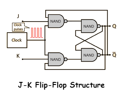
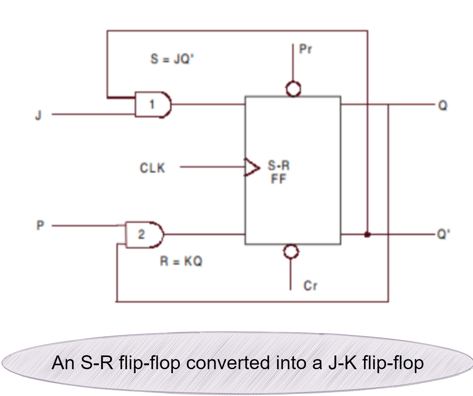
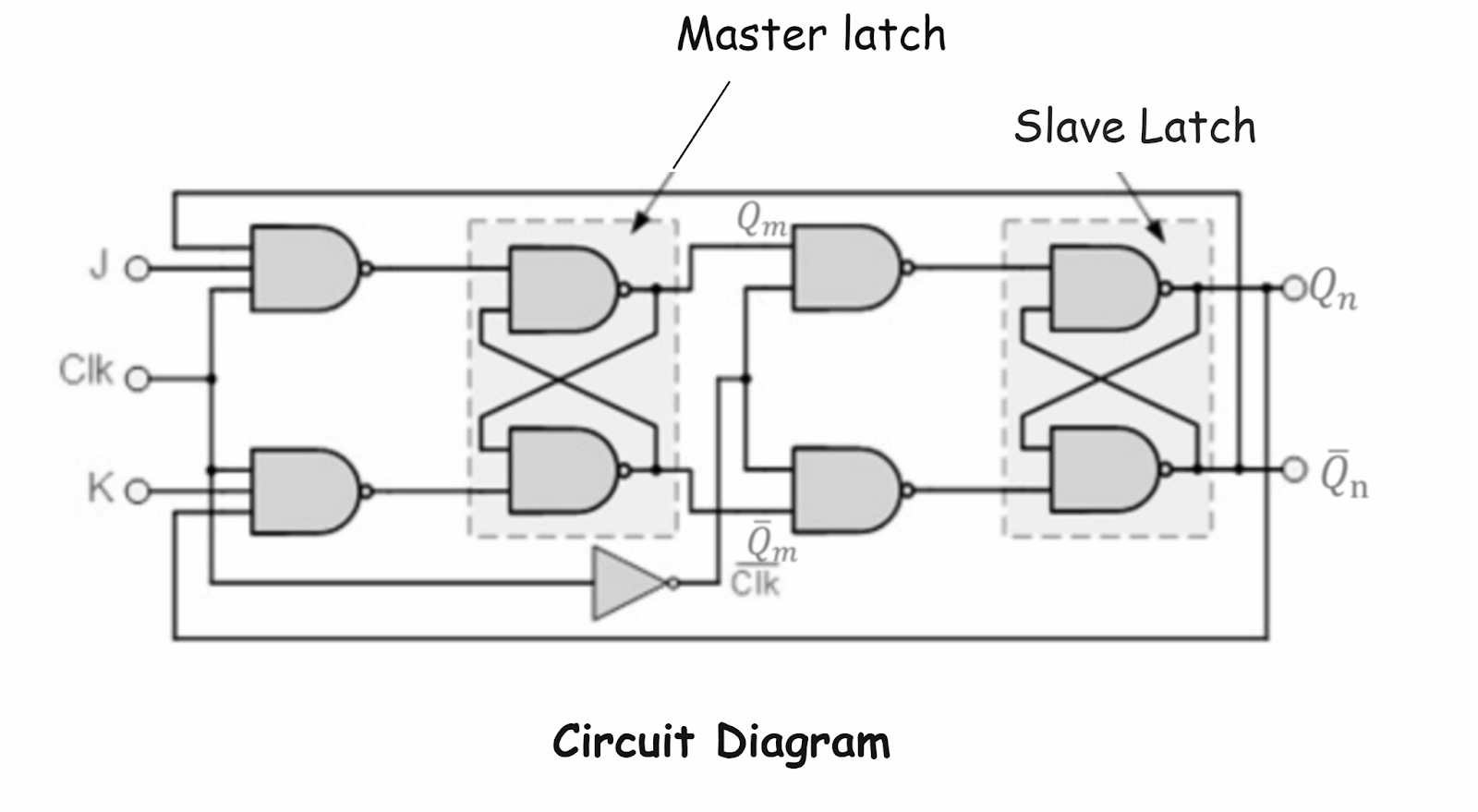
When J = K = 1, the flip flop is in a toggle state, which means the output switches to its complementary state every time a clock passes. The data inputs are J and K, which are ANDed with Q' and Q respectively to obtain the inputs for S and R. A J-K flip flop thus obtained is shown in Figure below. 

JK flip flop structure

The only difference between SR and JK flip-flop is that when both inputs of SR flip flop is set to value 1, the circuit produces an output as the invalid states, but in the case of JK flip flop, there are no invalid states even if both 'J' and 'K' flip flops are set to value 1.


JK flip flop

JK flip-flop Truth table 


JK flip-flop Truth table

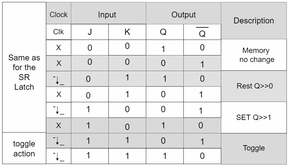
Case 1: When the clock is applied and J = 0, whatever the value of Q'n (0 or 1), the output of NAND gate 1 is 1. Similarly, when K = 0, whatever the value of Qn (0 or 1), the output of gate 2 is also 1. Therefore, when J = 0 and K = 0, the inputs to the basic flip-flop are S = 1 and R = 1. This condition forces the flip-flop to remain in the same state. 

Case 2: When the clock is applied and J = 0 and K = 1 & the previous state of the flip-flop is reset (i.e., Qn = 0 and Q'n = 1), then S = 1 and R = 1. Since S = 1 and R = 1, the basic flip-flop does not alter the state and remains in the reset state. But if the flip-flop is in set condition (i.e., Qn = 1 & Q'n = 0), then S = 1 and R = 0. Since S = 1 and R = 0, the basic flip-flop changes its state and resets. 

Case 3: When the clock is applied and J = 1 and K = 0 and the previous state of the flip-flop is reset (i.e., Qn = 0 and Q'n = 1), then S = 0 and R = 1. Since S = 0 and R = 1, the basic flip-flop changes its state and goes to the set state. But if the flip-flop is already in set condition (i.e., Qn = 1 and Q'n = 0), then S = 1 and R = 1. Since S = 1 and R = 1, the basic flip-flop does not alter its state and remains in the set state.

Case 4: When the clock is applied and J = 1 and K = 1 and the previous state of the flip-flop is reset (i.e., Qn = 0 and Q'n = 1), then S = 0 and R = 1. Since S = 0 and R = 1, the basic flip-flop changes its state and goes to the set state. But if the flip-flop is already in set condition (i.e., Qn = 1 and Q'n = 0), then S = 1 and R = 0. Since S = 1 and R = 0, the basic flip-flop changes its state and goes to the reset state. So we find that for J = 1 and K = 1, the flip-flop toggles its state from set to reset and vice versa.  

Must Read Shift Registers in Digital Electronics

Master-Slave JK Flip-flop

Basically, a master-slave flip-flop is a system of two flip flops—one being designated as the master and the other being the slave. The figure III below shows that a clock pulse is applied to the master, and the inverted form of the same clock pulse is applied to the slave. When    CLK = 1, the first flip-flop (i.e., the master) is enabled, and the outputs Qm and Q'm respond to the inputs J and K according to the table shown.

At this time, the second flip flop (i.e., the slave) is disabled because the CLK is LOW to the second flip flop. Similarly, when CLK becomes LOW, the master becomes disabled, and when the slave becomes active. Therefore, the outputs Q and Q' follow the outputs Qm and Q'm respectively.

Since the second flip-flop just follows the first one, it is referred to as a slave, and the first one is called the master. Hence, the configuration is referred to as a master-slave (M-S) flip-flop. 


 Master-Slave JK Flip-flop

Fig I


Master-Slave JK Flip-flop

Fig II


Circuit Diagram

Fig III

The state of the master-slave flip-flop, shown in the figure given above, changes at the negative transition (trailing edge) of the clock pulse. Hence, it becomes negative triggering a master-slave flip-flop. This can be changed to a positive edge triggering flip-flop by adding two inverters to the system - one before the clock pulse is applied to the master and an additional one in between the master and the slave. 

The logic symbol of a negative edge master-slave is shown in the figure given below. The system of master-slave flip-flops is not restricted to J-K master-slave only. There may be an S-R master-slave or a D master-slave, etc., in all of them the slave is an S-R flip-flop, whereas the master changes to J-K or S-R or D flip-flops. 

Characteristic Table:

CP

0→1 

1→0

0→1

1→0

0→1

1→0 

0→1

1→0


0

0

0

0

1

1

1

1


0

0

1

1

0

0

1

1


Qm 

Hold

Hold

0

Hold

1

Hold

Toggle 

Hold


Q’m

Hold

Hold

1

Hold

0

Hold

Toggle 

Hold


 Qn

Hold

Hold

Hold

0

Hold

1

Hold

Toggle 


Q’n

Hold

Hold

Hold

1

Hold

0

Hold

Toggle 


Applications of JK Flip-Flop

  • Counters: Used in binary, ripple, and up/down counters due to their ability to toggle states.
     
  • Registers: Helps in designing shift registers, which store and shift data in sequential circuits.
     
  • Memory Units: Used in RAM and other storage devices to retain binary data.
     
  • Frequency Division: Divides input clock frequency by two, making it useful in clock division circuits.
     
  • Control Circuits: Utilized in control systems for state transitions and event detection.

Advantages of JK Flip-Flop

  • No Invalid State: Unlike the SR flip-flop, the JK flip-flop eliminates the indeterminate state, ensuring reliable operation.
     
  • Toggle Feature: It can function as a T flip-flop, making it highly useful in designing counters and frequency dividers.
     
  • Versatility: Supports multiple applications in digital circuits, including sequential logic designs, shift registers, and memory units.

Disadvantages of JK Flip-Flop

  • Timing Issues: At higher clock speeds, the JK flip-flop can experience race conditions, leading to unstable outputs.
     
  • Increased Circuit Complexity: Compared to SR flip-flops, it requires more gates and connections, making implementation more complex.
     
  • Power Consumption: More logic elements result in higher power usage, which can be a drawback in low-power applications.

Frequently Asked Questions

What is a clock in a flip flop?

A clock pulse is a time-varying voltage signal that controls a flip flop's operation (triggering). For exp, if a clock pulse is of frequency 1 Hz, the voltage it will supply will oscillate between X Volts and Y Volts(X and Y are any dc voltages), and this change occurs every half second.

What is the status of Q output when J= 1 and k= 0?

If inputs of J and K are both LOW (J = K = 0), there will be no change in Q, no matter how many times the clock pulse is applied. If K = 1 (HIGH) and J = 0 (LOW) the next clock edge resets Q output LOW (Q = 0). If K = 0 and J = 1, then the next clock edge sets Q output HIGH (Q = 1).

How is a J-K flip-flop made to toggle? 

When j=k=1, the race condition occurs, which means both outputs want to be HIGH. Hence, there is a toggle condition where 0 becomes 1 and 1 becomes 0. That is device is either reset or set.

What is the toggle condition?

Condition of a flip-flop circuit in which the internal state of the flip-flop changes from value 0 to 1 or from 1 to 0.

What is J in JK flip-flop?

The JK flip flop was named after Jack Kilby, the Texas Instruments engineer who invented the integrated circuit in 1958. In his honor, the modified RS circuit that eliminated race conditions was named JK.

Conclusion

In this article, we discussed the JK flip-flop, a fundamental sequential circuit widely used in digital electronics. We discussed its working principle, truth table, and characteristic equation. Unlike other flip-flops, the JK flip-flop eliminates the indeterminate state present in the SR flip-flop, making it more reliable for various applications. With its ability to toggle states and store binary information, the JK flip-flop is extensively used in counters, registers, and memory devices. Understanding its operation is essential for designing efficient digital circuits.

Live masterclass