Do you think IIT Guwahati certified course can help you in your career?
Introduction
This blog will discuss logic gates and the different types of logic gates. But before learning about different types of logic gates, we should first look at what are logic gates and why logic gates were needed in the first place.
Logic gates are used in computers to convert 1s and 0s from input wires. A logic gate receives inputs and then outputs a result based on the state of those inputs.
What is the use of logic gates?
Logic gates are the basic building blocks of digital systems.
They perform logical operations on binary inputs (0s and 1s).
Each gate produces a single binary output based on input conditions.
Logic gates operate using Boolean algebra, which defines logical relationships between inputs and outputs.
Role in Digital Communication
Data is sent to computers as 1s and 0s via wires.
Logic gates help process and manipulate these binary digits.
Enable both simple and complex operations, like calculating the 50th decimal of π.
Where Logic Gates Are Used
Found in almost every modern digital device, including:
Smartphones
Computers
Tablets
Memory units
Key Concepts to Understand Logic Gates
To understand how logic gates work, it’s helpful to explore some basic concepts like:
Boolean algebra
truth tables
Logic gate symbols are often illustrated in flowcharts for easier comprehension.
We will be discussing about each of the logic gates in the following sections.
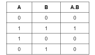
AND Gate
Truth Table
The AND gate is an electrical circuit that only outputs a high value (1) if its inputs are also high. The AND operation, i.e., A.B., is represented by a dot (.). Remember that this dot is occasionally deleted, as in AB.
Properties of AND Gate
Multiple Inputs An AND gate can take two or more input signals. All inputs must be considered when determining the output.
Output is High Only When All Inputs Are High The AND gate gives an output of logic 1 (HIGH) only if all inputs are also 1. If any input is 0, the output becomes 0.
OR Gate
Truth Table
An OR gate is a logic gate that performs a logical OR operation. The logical OR operation gives a high output if one or both of the gate's inputs are high (1). (1). The outcome is a low output if neither of the inputs is high (0). An OR gate can only have one output probe, similar to how an AND gate may have an infinite number of input probes.
Properties of OR Gate
Here are the core properties of an OR gate, explained clearly and concisely:
Accepts Two or More Inputs An OR gate can take two or more input signals. It evaluates all the inputs to determine the final output.
Output is Low Only When All Inputs Are Low The OR gate gives an output of logic 0 (LOW) only when all inputs are 0. If at least one input is 1, the output becomes logic 1 (HIGH).
These properties make the OR gate useful for decision-making in digital circuits.
NAND Gate
Truth Table
This is a NOT-AND gate, a combination of an AND gate and a NOT gate. If any of the inputs is low, the outputs of all NAND gates are high. An AND gate with a little circle on the output is the symbol. The little circle represents inversion.
Properties of NAND Gate
Accepts Two or More Inputs and Gives One Output A NAND gate can take two or more input signals and provide a single output based on those inputs.
Outputs 0 Only When All Inputs Are 1 The output of a NAND gate is logic 0 only when all inputs are logic 1. In any other case, the output is logic 1.
These properties make the NAND gate a universal gate in digital electronics.
NOR Gate
Truth Table
This is a NOT-OR gate, a combination of an OR gate and a NOT gate. If any of the inputs is high, the outputs of all NOR gates are low.
An OR gate with a little circle on the output is the symbol. The little circle represents inversion.
Properties of NOR Gate
Accepts Two or More Inputs A NOR gate can take two or more input signals and processes them to give a single output.
Produces Logic 1 Only When All Inputs Are 0 The output is logic 1 only when all inputs are at logic 0. If any input is logic 1, the output becomes logic 0.
NOT Gate
Truth Table
The NOT gate is a kind of electrical circuit that outputs an inverted version of the input. An inverter is another name for it. The inverted output is NOT A if the input variable is A. As shown at the outputs, this is also displayed as A', or A with a bar over the top. The illustrations below demonstrate two different methods to arrange the NAND logic gate to form a NOT gate. In the same manner, it may be done using NOR logic gates.
Properties of NOT Gate
Produces the Complement of the Input The NOT gate outputs the opposite logic level of its input. If the input is 1, the output is 0, and vice versa.
Accepts Only One Input It is a single-input, single-output gate that performs the inversion operation on that input.
XOR Gate
Truth Table
In an XOR gate, the output of a two-input XOR gate achieves state 1 if just the input is added.
The Boolean expression of the XOR gate is
Properties of XOR Gate
Accepts Only Two Inputs at a Time The XOR (Exclusive OR) gate works with two input signals and produces a single output.
Outputs Logic 1 When Inputs Are Different It gives a high output (1) only when one input is 1 and the other is 0. If both inputs are the same, the output is 0.
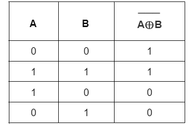
XNOR Gate
Truth Table
The XNOR gate is the XOR gate's opposite. The output level is high only when both of the XNOR gate's inputs are the same, either 0 or 1.
Takes Two Inputs and Produces One Output The XNOR (Exclusive NOR) gate works with two input signals and returns a single output based on their comparison.
Outputs Logic 1 When Inputs Are the Same It gives a high output (1) only when both inputs are identical—either 0 and 0 or 1 and 1.
Applications of Logic Gates
Computers: Logic gates are used to perform binary calculations in CPUs and ALUs.
Microprocessors: They control data flow and execute instructions in digital circuits.
Microcontrollers: Logic gates help automate control in embedded systems.
Smartphone Sensors: Used in proximity sensors and gesture recognition.
Digital Clocks: Manage timekeeping operations and alarm triggers.
Logic gates are essential in all modern electronic devices for decision-making and control.
Advantages of Logic Gates
Operate faster than mechanical relays or analog systems.
Perform accurate logical operations with minimal errors.
Easy to integrate into digital circuits and microchips.
Require less physical space compared to older systems.
Enable automation in computing and electronic devices.
Provide reliable and consistent output signals.
Use low voltage levels, making them energy efficient.
Compatible with modern digital components and architectures.
It allows complex operations through combinations of simple gates.
Support high-speed processing in digital electronics like CPUs and microcontrollers.
Disadvantages of Logic Gates
Circuit complexity increases with the number of gates.
Propagation delay may occur in multi-gate systems.
Sensitive to electrical noise, which may cause errors.
Continuous switching can lead to power loss and heat generation.
Frequently Asked Questions
What are the applications of Logic Gates?
The applications of logic gates are many, but they are mostly determined by their mode of operation or truth table. Basic logic gates may be found in a safety thermostat, a push-button lock, an automated watering system, a light-activated burglar alarm, and a variety of other electronic devices. If the processes are advanced, one of the key advantages is that simple logic gates may be employed in various combinations. Furthermore, the number of gates employed in a single device is unlimited. However, it may be limited due to the device's physical limitations. A logic gate area unit array may be found in digital integrated circuits (I.C.s).
What is DeMorgan’s Law?
De Morgan's Law states that the complements of two sets are the complements of their complements and that the complements of two sets are the complements of their complements. De Morgan, a talented mathematician, was the inspiration for them. (A B)' = A'B'is the formula for this law. The set theory uses complements to link the intersection and union of sets.
What is an Adder?
In electronics, an adder is a digital logic circuit often used to add integers. Adders are used in many computers and other kinds of processors to calculate addresses and associated actions and construct table indices in the ALU and other portions of the CPU. Many number representations, such as excess-3 or binary coded decimal, may be formed using them.
Conclusion
This article briefly discussed different types of gates.
I hope that you must have gained some insight into this topic of Logic gates and if you want to learn more then you can refer to this blog.


 9+ registered

