


Introduction
In this blog, we will discuss about logic gates & circuits.
Logic Gates
Logic gates are the basic unit used to build any digital system around us. It helps in making decisions by producing outputs for different combinations of given inputs. The inputs and outputs of logic gates can occur only in two levels: HIGH and LOW, MARK and SPACE, TRUE and FALSE, ON and OFF, or simply 1 and 0. A Boolean expression will represent the function of each logic gate.
Classification of Logic Gates
Logic gates can be classified as:
- Basic Gates - NOT, AND, OR
- Universal Gate - NAND, NOR
- Special Purpose Gate - EX-OR, EX-NOR
A truth table helps in describing the logic circuit’s output based on the circuit’s input.
To read about logic gates and circuits in detail click here.
Must Read, 8085 Microprocessor Pin Diagram
Types of Logic Gates
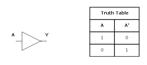
NOT Gate
- Referred to as inversion or complementation
- Single input variable
- Single output variable
- Output is always opposite to the input.
- Represented by the bar(―) or (‘).
- In the below-given figure, A is the input, and Y is the output. The left side shows the circuit diagram, and the right side shows the truth table.
Credit: notesformsc
Algebraic expression: Y = NOT A.
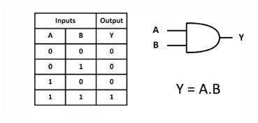
AND Gate
- Two or more input variable
- Single output variable
- Represented by dot (.) or (Ʌ).
- If at least any of the one input is low(0), then output is 0.
- In the below-given figure, A and B are the input, and Y is the output. The right side shows the circuit diagram, and the left side shows the truth table.
Credit: signoffsemi
Algebraic expression: Y = A.B
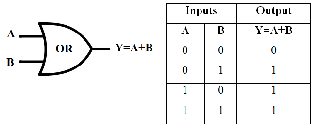
OR Gate
- Two or more input variable
- Single output variable
- Represented by dot (+) or (V).
- If at least one input is high(1), then output is 1.
- In the below-given figure, A and B are the input, and Y is the output. The left side shows the circuit diagram, and the right side shows the truth table.
Credit:electronicsclub
Algebraic expression: Y = A+B
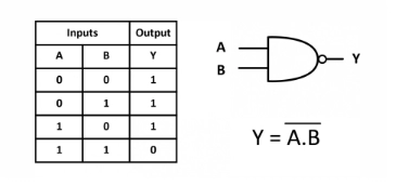
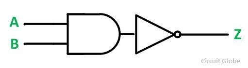
NAND Gate
- Two or more input variable
- Single output variable
- Output is always opposite to the output obtained in the case of AND gate.
- Represented by dot (.) followed by a bar (―) on top.
- If at least any of the one input is low(0), then output is 1.
- In the below-given figure, A and B are the input, and Y is the output. The right side shows the circuit diagram, and the left side shows the truth table.
Credit: signoffsemi
Algebraic expression: Y = NOT(A.B)
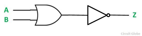
NOR Gate
- Two or more input variable
- Single output variable
- Output is always opposite to the output obtained in the case of the OR gate.
- Represented by a plus (+) followed by (―) on top.
- If at least one input is high(1), then output is 0.
- In the below-given figure, A and B are the input, and Y is the output. The left side shows the circuit diagram, and the right side shows the truth table.
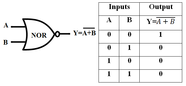
Credit:electronicsclub
Algebraic expression: Y = NOT(A+B)
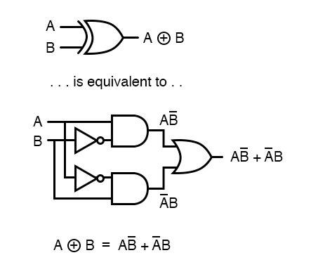
EX-OR Gate
- Two input variable
- Single output variable
- Represented by a plus (+) encircled by a circle.
- If only and only one input is high(1), then output is 1.
- Used in parity generation and detection.
- In the below-given figure, A and B are the input, and Y is the output. The left side shows the circuit diagram, and the right side shows the truth table.
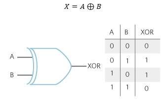
Credit:maximintegrated
EX- NOR Gate
- Also called the gate of equivalence or coincidence logic.
- This is an XOR gate followed by NOR gate.
- Two input variable
- Single output variable
- Represented by dot (.) encircled by a circle.
- If only and only one input is high(1), then output is 0.
-
In the below-given figure, X and Y are the input, and Z is the output. The left side shows the circuit diagram, and the right side shows the truth table.
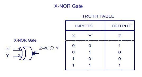
Credit:pinimg


 9+ registered

