Do you think IIT Guwahati certified course can help you in your career?
Introduction
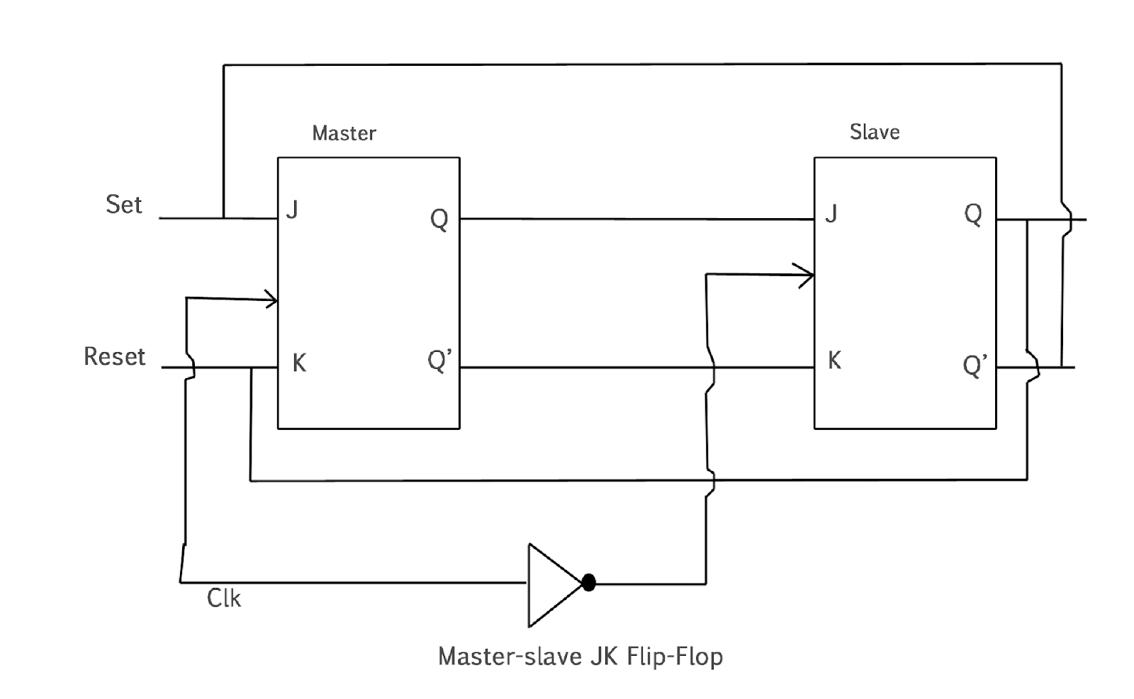
A master-slave flip flop is made by connecting two JK flip flops in a series configuration in which one acts as the master and another as a slave. The two inputs of slave are connected with the output of the master flip flop. Furthermore, the master flip flop inputs are fed back by the output of the slave flip flop. Apart from two flip-flops, it has one inverter. Here inverter and clock pulse are connected to ensure that the slave flip flop gets an inverted clock pulse. If CP = 0 for the master flip flop, CP=1 for slave flip flop, and vice versa.
What is a Master-Slave JK Flip Flop?
A Master-Slave JK flip-flop is a type of digital circuit used in electronics to store one bit of data. It is composed of two interconnected flip-flops: a master flip-flop and a slave flip-flop.
Master Flip-Flop: The master flip-flop is sensitive to the clock signal. When the clock signal transitions from low to high (also known as the rising edge), the master flip-flop reads the inputs and stores the data temporarily. In the case of a JK flip-flop, the inputs are J (data input) and K (clear input).
Slave Flip-Flop: The slave flip-flop, on the other hand, is sensitive to the opposite phase of the clock signal (i.e., the falling edge). When the clock signal transitions from high to low (the falling edge), the slave flip-flop reads the data stored in the master flip-flop and retains it until the next clock cycle.
Working of Master-Slave Flip Flop
In this section, we are going to see the working of Master-slave flip flop-
The slave is isolated when the clock pulse is 1, and the system's state can be affected by J and K inputs. Slave remains isolated until the clock pulse changes to 0. When the clock pulse is one, the information is passed to the slave from the master flip flop, obtaining output.
At the initial stage, the master flip flop is positive level triggered, and the slave flip flop is negative level triggered. That's why master flip flop responds before slave flip flop.
When J=0 and K=1, then K of slave flip flops gets the high 'Q' output of the master flip flop, and slave resets when the clock forces it to do so for copying the master.
When J=1 and K=0, J input of slave flip flop gets high 'Q' output of master flip flop, the slave is set by a negative clock transition, copying the master.
When J=1 and K=1, It toggles the clock's positive transition, enabling the slave to toggle its negative transition.
The flip flop is disabled when J=0 and K=0, and Q remain unchanged.
Operation of Master-Slave JK Flip Flop
A Master-Slave JK Flip Flop consists of two JK flip-flops connected in series—one acts as the master, and the other as the slave. It eliminates race-around conditions by using a clock pulse to control data flow.
How It Works
Master Stage: The master flip-flop captures the input (J and K) when the clock is high.
Slave Stage: The slave flip-flop copies the master’s output when the clock goes low.
Avoids Race Condition: Changes in output occur only at the falling edge of the clock, ensuring stable performance.
This mechanism ensures proper synchronization, making it useful in sequential circuits.
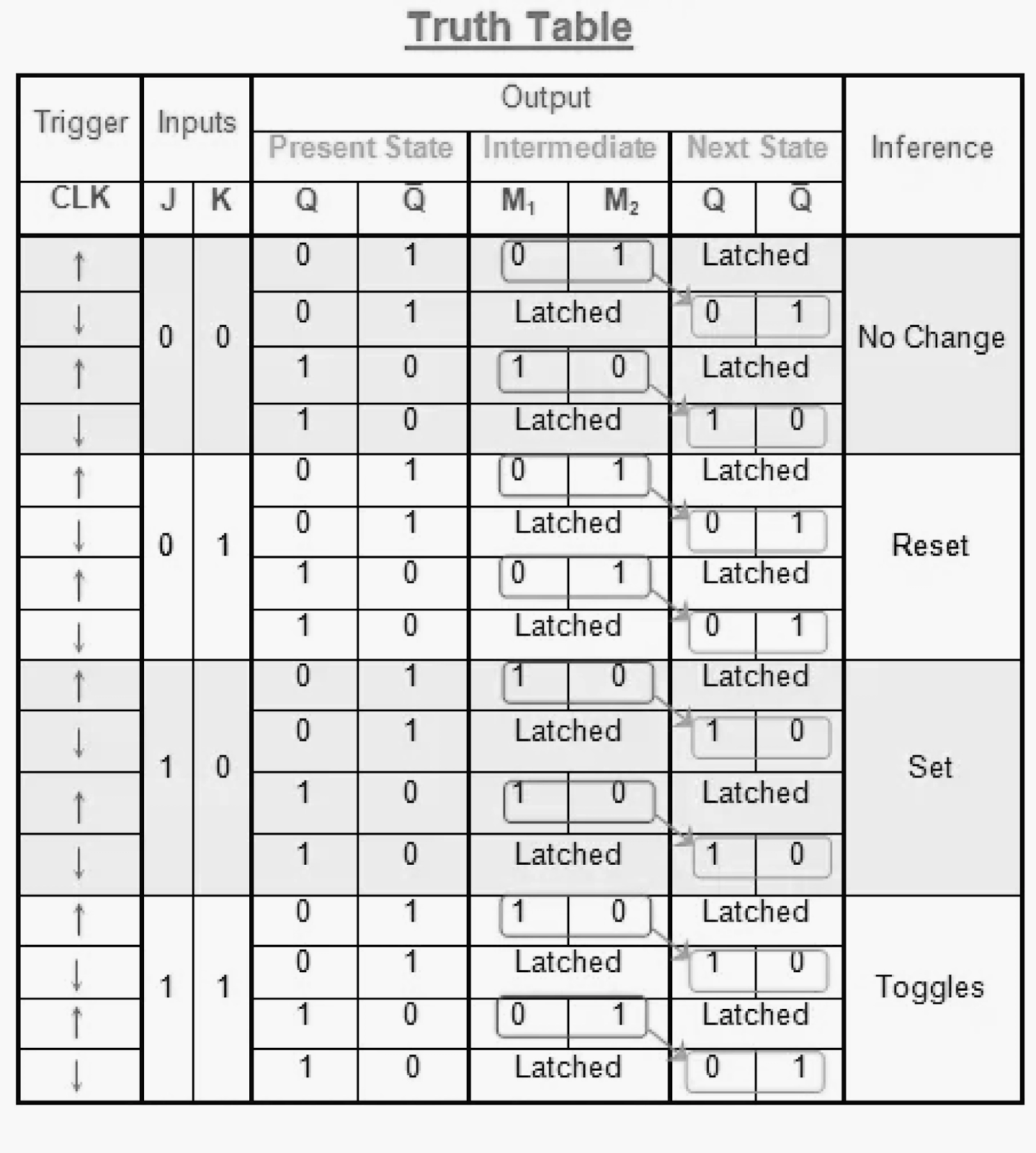
Truth Table of Master-Slave JK Flip Flop
Characteristic Table
Inputs
Output
J
K
Q
Q`
D
0
0
0
0
0
0
0
1
1
1
0
1
0
0
0
0
1
1
0
0
1
0
0
1
1
1
0
1
1
1
1
1
0
1
1
1
1
1
0
0
Use of Master-Slave Flip Flop
While using a JK flip flop when J = K = 1 and CLK (clock) = 1 for an extended period, then for the time duration the clock is high, and output Q will toggle, resulting in unstable/uncertain flip flop's output. This problem is known as the Race around condition in the JK flip flop.
But to avoid this situation/problem, we ensured that the CLK = 1 for a short period and introduced the master-slave JK flip flop concept.
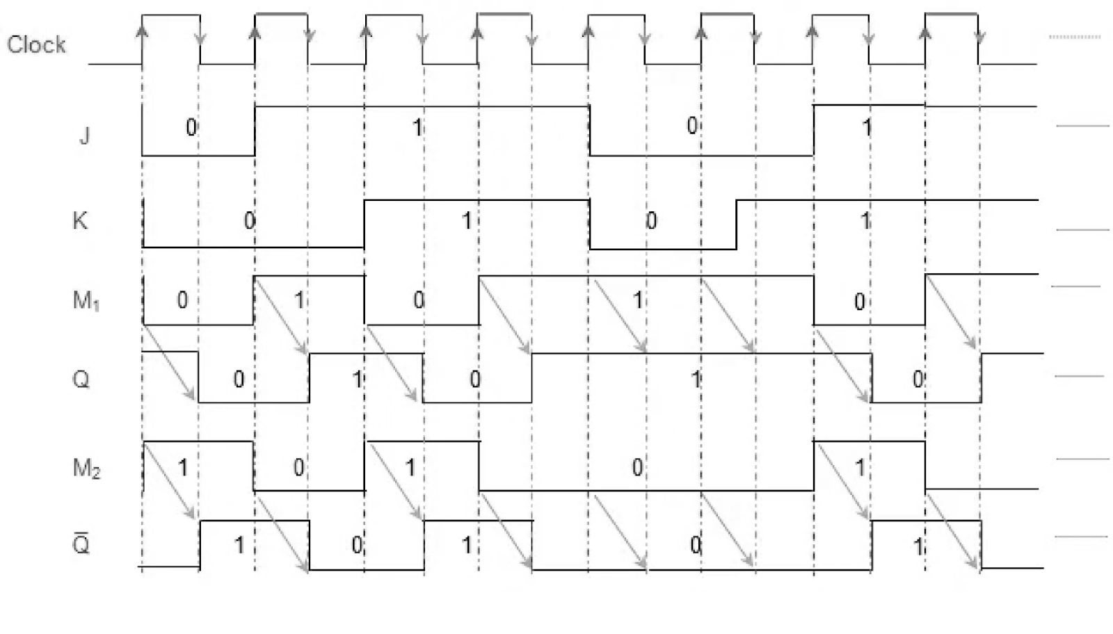
Timing Diagram of a Master Flip Flop
The output of the master flip flop remains one when the clock pulse is set to one until the clock input remains 0.
The master flip flop output is 0 when the clock pulse becomes high again. But when the clock becomes one again, it sets to one.
When the clock pulse is 1, the master flip flop is operational. Until the clock pulse is set to zero, the output of the slave flip flop remains zero as it is not operational.
When the clock pulse is zero, the slave flip flop is operational. Until the clock is set to zero again the master flip flop's output remains one.
Output changes once in a cycle; hence toggling occurs throughout the entire process.
Advantages of Master-Slave Flip Flop
We can operate master-slave flip flops on level-triggered or edge-triggered clock pulse. We can use it in various ways.
A sequential circuit with a level-triggered flip flop is challenging to design, but edge triggered flip flop is easy to design.
Most importantly, we can eliminate the Race around condition using the master-slave flip flop configuration.
Disadvantages of Master-Slave Flip Flop
Increased Circuit Complexity: Master-slave flip flops use two latches connected in series, which increases the overall complexity of the circuit compared to a single flip flop.
Slower Operation: Due to the sequential nature of master and slave stages, there is a slight delay in data propagation, making them slower than simpler flip-flops in high-speed circuits.
More Hardware Resources: They require more components (like gates and latches), leading to higher hardware resource usage in large-scale digital systems.
Power Consumption: The additional components and transitions between master and slave stages can lead to slightly higher power consumption.
Limited to Edge-Triggered Applications: While they help eliminate race conditions, they are primarily suited for edge-triggered designs and may not be ideal for all level-sensitive applications.
The master-slave configuration consists of two interconnected flip-flops: the master, which reads inputs on the rising edge of the clock, and the slave, which reads data from the master on the falling edge.
Why should we use master-slave flip flop?
Master-slave flip-flops enhance digital circuit reliability by reducing metastability, providing edge-triggered operation, and improving noise immunity. They are essential for synchronized, sequential signal processing and better timing control in complex digital systems.
What is a master-slave flip flop made up of?
A master-slave flip-flop consists of two interconnected flip-flops. The master flip-flop captures data on the rising edge of the clock signal, while the slave flip-flop captures this data on the falling edge, providing more stable and reliable sequential logic behavior.
Conclusion
We learned about Master Slave Flip Flop in this blog, including its truth table and the characteristic table. We learned about its advantages and why we should use it. We also went through the timing diagram of the master-slave flip flop.


 8+ registered

