Do you think IIT Guwahati certified course can help you in your career?
Introduction
In this blog, we will discuss the microinstructions format.
Each step in a sequence of steps in executing a certain machine instruction is considered a microinstruction, and a control word represents it.
Example:
ADD R1, X
The above statement means that the content of a memory X is added to R1, and then this is stored at register R1. This operation is not done in a single step. The steps involved in performing this simple operation are:
The value at X is first stored in the memory address register. i.e., MAR=X.
The value of the memory address register goes to the memory’s address line, and the contents present there are stored in the memory data register.
Then this data register’s value is added to R1.
Finally, the obtained result is stored in register R1.
So the simple instruction ADD R1, X follows multiple steps to execute itself.
What is Microinstructions Format
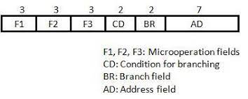
The 20 bits present in microinstruction are divided into four main functional parts as follows:
Three micro-operation fields each of 3 bits. (11th, 12th and 13th bit for F3, 14th, 15th and 16th bit for F2, 17th, 18th and 19th bit for F1)
one condition for branching field of 2 bits. (9th bit and 10th bit)
one branch field of 2 bits. (7th bit and 8th bit)
one address field of 7 bits. (from 0th bit to 6th bit) Click here to read about, Data Warehouse Architecture
Symbols with their Binary Code for Microinstruction Fields
Name
Code
Symbol
F1
000
None
NOP
001
AC ← AC + DR
ADD
010
AC ← 0
CLRAC
011
AC ← AC + 1
INCAC
100
AC ← DR
DRTAC
101
AR ← DR(0 − 10)
DRTAR
110
AR ← PC
PCTAR
111
AC ← AC + DR
WRITE
F2
000
None
NOP
001
AC ← AC + DR
SUB
010
AC ← AC ∨ DR
OR
011
AC ← AC ∧ DR
AND
100
DR ← M[AR]
READ
101
DR ← AC
ACTDR
110
DR ← DR + 1
INCDR
111
DR(0 − 10) ← PC
PCTDR
F3
000
None
NOP
001
AC ← AC ⊕ DR
XOR
010
AC ← AC′
COM
011
AC ← shl AC
SHL
100
AC ← shr AC
SHR
101
PC ← PC + 1
INCPC
110
PC ← AR
ARTPC
111
DR(0 − 10) ← PC
Reserved
Micro operation field
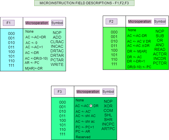
The 3 bits in each field are encoded to specify 7 distinct micro-operations plus one idle micro-operation (i.e: no operation). This gives a total of 21 micro-operations. We already know that if n bits are given, we can perform 2^n operations.
A microinstruction includes 3 micro-operation, one for each field, so no more than 3 micro-operations can be selected for a microinstruction. If the micro instruction needs micro-operations less than 3, one or more of the micro-operation fields will be occupied by a binary code 000 for no operation.
Starting with the F1 instruction field, we know that each field supports a total of 8 operations. Out of this, one operation 000 remains idle(i.e., no operation). 001 performs the addition of contents of the accumulator and data register, and the result is stored in the accumulator. 010 performs a clear accumulator operation. 011 performs increase accumulator operation. 100 performs the operation of transferring the content of the data register to the accumulator. 101 performs the operation of transferring the content of the data register to the address register. 110 Performs the operation of transferring the content of the program counter to the address register. 111 performs the operation of transferring the content of the data register to the memory address of the address register.
Now, in the F2 instruction field, 000 performs no operation. 001 performs subtraction of contents of accumulator and data register, and the result is stored in the accumulator. 010 performs the OR operation between accumulator and data register and stores the result in the accumulator. 011 performs the AND operation between accumulator and data register and stores the result in the accumulator. 100 performs the read operation. 101 performs the operation of transferring the content of the accumulator to the data register. 110 performs increase data register operation. 111 performs the operation of transferring the content of the program counter to the data register.
In the F3 instruction field, 000 performs no operation. 001 Perform the XOR operation of accumulator and data register and store the result in the accumulator. 010 performs the complement operation of the accumulator. 011 performs left shift operation on the accumulator. 100 performs right shift operation on the accumulator. 101 performance increment program counter operation. 110 performs the operation of transferring the value of the address register to the program counter. 111 is used for reserved purposes.
Condition Field
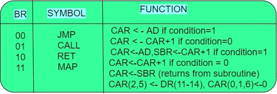
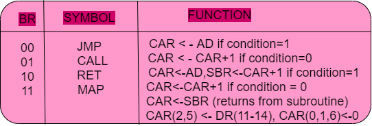
This microinstruction field select status bit conditions. It consists of 2 bits which are encoded to specify 4 status bit conditions.
The BR field, which consists of two bits, specifies the type of branch used. This branch field is used in conjunction with the address field AD to choose the following microinstruction address.
The abbreviations used above implies:
JMP - jump.
CAR - control address register.
AD - address.
CALL - call a subroutine.
SBR - subroutine register.
RET - return
MAP - mapping.
DR - Data register.
Address field
This is an address field that contains a branch address. This field is of 7 bits since control memory has 128 words. It may contain symbolic addresses, NEXT, empty.
Symbolic Microinstructions
This provides symbols for each field of the microinstruction and allows users to create their own symbolic addresses to create an assembly language for a microprogram quickly and easily. The symbolic microinstructions are divided into five fields each.
The five fields are the label field, the microoperation field, the condition field, the branch field, and the address field.
Control signals associated with operations are stored in a special memory unit inaccessible by the programmer as control words. Each individual bit of the control word represents the various control signal.
Differentiate between micro-operation and micro-instruction.
Instructions present in control memory are called microinstructions, whereas the atomic operations that execute a particular microinstruction are called micro-operation.
What is the program counter? What is the status bit?
The program counter is generally used to store the address of the next instruction to be performed. Status is used to update the state of a particular instruction.
What are the two types of Microinstruction formats?
Vertical microcode and Horizontal microcode are the two different forms of microinstruction formats. In vertical microprogramming, the control bits are encoded using separate codes for each operation to be carried out. Without any encoding, horizontal microinstructions are used in horizontal microprogramming.
Conclusion
This article taught us about the microinstructions format.
We hope you could easily take away all critical and conceptual techniques by walking over the given examples.
Now, we strongly recommend you to understand the other related concepts in Computer Organization and Architecture and enhance your learning. You can get a wide range of topics similar to this on guided paths.


 8+ registered

