Do you think IIT Guwahati certified course can help you in your career?
Introduction
Hey Ninja!! Welcome back to yet another article!!! Before going on to the 8257 DMA Controller, let's first understand what a DMA Controller is.
DMA, or Direct Memory Access Controller, is an external device that manages data transmission between I/O devices and memory without involving the processor. It may directly access the main memory for reading or writing operations.
Intel built the DMA controller to have a fast data transfer rate while using the lowest amount of processor power.
Using a DMA controller, the device requests that the CPU retain its data, address, and control buses to transport data directly to and from memory.
The DMA data transmission begins only once the CPU receives the HLDA signal.
The DMA Operation transaction process is as follows:
When a device needs to transmit data to memory, it must first submit a DMA request (DRQ) to the DMA controller.
The DMA controller sends the CPU a Hold request (HRQ) and waits for the CPU to assert the HLDA (HOLD Acknowledge) signal.
The microprocessor then “tri-states”(adding a third state to the binary logic) all data buses, address buses, and control buses. The CPU will give up the bus and acknowledge the HOLD request through the HLDA signal.
The CPU is now in HOLD mode, and the DMA controller must supervise bus activities between memory interfaced with the microprocessor and I/O devices.
Features of 8257
The 8257 is a direct memory access (DMA) controller that is designed to improve the data transfer rate between external devices and the microprocessor. Some of the key features of the 8257 microprocessor are:
Four independent DMA channels: The 8257 has four independent DMA channels, which can transfer data to or from four different devices simultaneously.
Address and data buses: The 8257 has its own address and data buses, which allow it to transfer data directly to and from memory without involving the microprocessor.
Burst mode transfer: The 8257 supports burst mode transfer, allowing it to transfer data blocks quickly and efficiently.
Priority schemes: The 8257 supports different priority schemes for each DMA channel, which allows the user to assign priorities to different devices based on their importance.
Auto-initialization: The 8257 supports auto-initialization, which allows it to automatically reload the DMA address and count registers after each data transfer.
Compatible with different microprocessors: The 8257 is compatible with a wide range of microprocessors, including the 8085, 8086, and Z80.
8257 DMA Controller
8257 is for a 4-channel DMA controller. Intel created it specifically for high-speed data transport. Its basic role is to produce a peripheral request, allowing the device to transmit data directly to/from memory without the CPU's involvement.
The device uses a DMA controller to submit requests to the CPU to store its data, sequential memory address, and control bus, allowing it to move data directly to/from memory. DMA data transfer begins after receiving the HLDA signal from the CPU.
The 8257 DMA Controller is a 4-channel, direct memory access controller that may be programmed. Each channel can be configured separately. As a result, we can connect four input/output devices to the 8257.
Each channel has a 16-bit DMA address register and a 14-bit counter. The DMA address register defines the memory location's address, while the counter specifies the number of DMA cycles to be done.
It keeps track of the DMA cycle count for each channel and sends a control signal TC (Terminal count) to the peripheral when the set number of DMA cycles is reached.
It employs priority logic to handle peripheral requests. The priority logic is designed to operate in fixed and rotating priority modes.
It can transport data in burst and cycle steal (single-byte transfer) modes.
It is capable of performing three DMA cycles: DMA read, DMA write, and DMA verify.
The 8257's auto-load features allow for Cipher block chaining (CBC).
It has two modes of operation: slave and master.
When DMA is in master mode, the AEN (Address enable) signal supplied by 8257 allows CPU buffers, latches, and other devices to be isolated from the system bus.
The extended write mode of 8257 reduces the occurrence of excess wait states in the Features of 8257, hence enhancing system performance.
It runs on a single TEL clock and is fully TEL-compatible.
It is compatible with all Intel processors.
It sends one byte of data per four clock cycles. As a result, with a 2 MHz clock input, a high transfer rate of 500 Kbytes/second is possible.
Like the 8085, the 8257 features a READY input that allows it to connect slower memory or I/O devices that cannot satisfy the 8257's bus setup timings.
Advantages and Disadvantages of DMA Controller
The following are the advantages and disadvantages of DMA controllers.
Advantages
DMA accelerates memory operations by avoiding the participation of the CPU.
The workload on the CPU is reduced.
Only a few clock cycles are required for each transmission.
Disadvantages
When DMA is utilized for data transport, a cache coherence problem might occur.
Increases the system's cost.
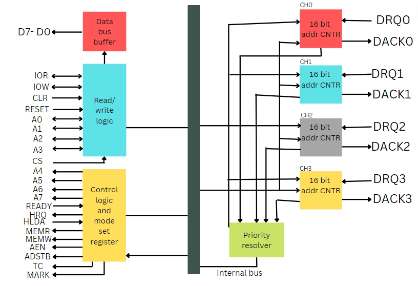
8257 DMA Controller Architecture
8257 DMA Controller Architecture consists of 7 different components: Data bus buffer, Read/Write logic, Control logic and mode set register, Channel 0, Channel 1, Channel 2, and Channel 3.
For more specifications, refer below figure.
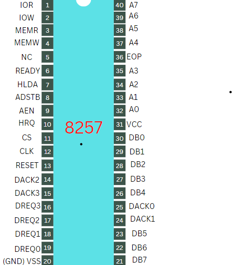
8257 DMA Controller Pin Description
The pin diagram of the 8257 DMA controller is shown below.
DB0 − DB7
These bidirectional data lines connect the system bus to the DMA controller's internal data bus. In Slave mode, It carries command words to 8257 and status words from 8257. These lines are utilized in master mode to send the higher address byte of the produced address to the latch. This address is then locked using the ADSTB signal.
A0 - A3
These are the four least significant address lines. They function as an input in the slave mode, selecting one of the registers to be read or written. They are the four least important memory address output lines generated by 8257 in master mode.
A4 - A7
In the master mode, this is the upper nibble of the lower byte address created via DMA.
DREQ0 − DREQ3
Peripheral devices utilize these four individual channel DMA request inputs to access DMA services. When the fixed priority mode is selected, DRQ0 is given the highest priority, and DRQ3 is given the lowest.
DACK0 - DACK3
These are the active-low DMA acknowledgment lines, which notify the requesting peripheral of the CPU's status of their request. These lines can also serve as beacon lines for the devices that want them.
IOR
It is an active-low bidirectional tri-state input line that the CPU uses in Slave mode to access the internal registers of the 8257. It is used in the master mode to read data from peripheral devices during a memory write cycle.
IOW
It is an active low bi-directional tri-state line that loads the data bus contents into the 8-bit mode register or upper/lower byte of a 16-bit DMA address register or terminal count register.
CLK
The internal operation of the 8257 requires a clock frequency signal.
RESET
This signal RESETS the DMA controller by turning off all DMA channels.
CS
It is a select chip line. It permits read/write operations to and from 8257 in Slave mode. It prevents read/write operations to/from 8257 while in master mode.
READY
It is an active-high asynchronous input signal that inserts wait states to make DMA ready.
HRQ
This signal is used to receive the output device's hold request signal. In slave mode, it is linked to DRQ input line 8257. In Master mode, it is coupled to the CPU's HOLD input.
HLDA
When set to 1, the hold acknowledgment signal informs the DMA controller that the CPU has granted the bus to the requesting peripheral.
MEMR
During DMA read cycles, the low memory read signal is utilized to read data from the designated memory locations.
MEMW
During a DMA write operation, the active-low three-state signal is utilized to write data to the specified memory region.
ADST
This signal transforms the DMA controller's upper byte of the memory address into latches.
AEN
This signal is used to turn off the address/data bus.
TC
It is an abbreviation for 'Terminal Count,' representing the current DMA cycle to the current peripheral devices.
MARK
The mark will be triggered every 128 cycles or integral multiples of 128 from the start. It denotes that the current DMA cycle is the 128th since the last MARK output to the specified peripheral device.
Vcc
It is the power signal that is necessary for the circuit to function.
Frequently Asked Questions?
What is a DMA Controller?
DMA, or Direct Memory Access Controller, is an external device that manages data transmission between I/O devices and memory without involving the processor. It may directly access the main memory for reading or writing operations.
What is the use of HLDA signals?
When HLDA Signal is set to 1, the hold acknowledgment signal informs the DMA controller that the CPU has granted the bus to the requesting peripheral.
What is the function of the AEN signal in the 8257 DMA Controller?
The function of the AEN signal in the 8257 DMA Controller is used to turn off the address/data bus.
What is the function of the ADST signal in the 8257 DMA Controller?
This signal transforms the DMA controller's upper byte of the memory address into latches.
What is the use of RESET Signal?
The use of RESET Signal is to RESETS the DMA controller by turning off all DMA channels.
Conclusion
In this article, we learned about the 8257 DMA controller and saw its architecture.
Before you close this page down, check out the articles our fellow ninjas wrote for you.


 9+ registered