Types of cardinality in ER diagram
- One to one cardinality.
- One to many cardinality.
- Many to many cardinality.
Symbols for cardinalities
- For one to one cardinality

- For one to many cardinality
- For many to many cardinality

Minimization in one-to-one cardinality in the ER diagram
The ONE-TO-ONE (1:1) RELATIONSHIP describes how one row in one database table relates to exactly one row in another database table.
1:1 means that the occurrence of an entity is related to one even of a second entity.
1:1 means that one occurrence of an entity is related to one event in a second entity.
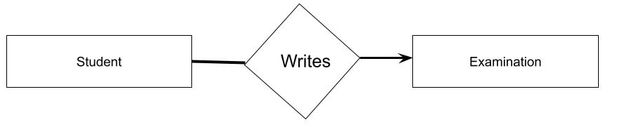
Let see the following diagram with one to one cardinality
If we look carefully at the upper part of the diagram, it represents three entities-The student entity has two attributes: Name and roll_num, where roll_num is the primary key. The examination entity has two attributes—Exam_id and subject, where exam_id is the primary key. The primary key of the write table can be Exam_id or roll_num, We cannot merge three tables into one table, but we can merge Write into student or examination. A one-to-one base cardinality requires at least two tables.

Minimization in one to many cardinalities in the ER diagram
A one-to-many relation describes the relationship between one row in a database table and many rows in a second table. Because primary keys and foreign keys are used to enforce this relationship, it is also known as a Primary Key-Foreign Key relationship.
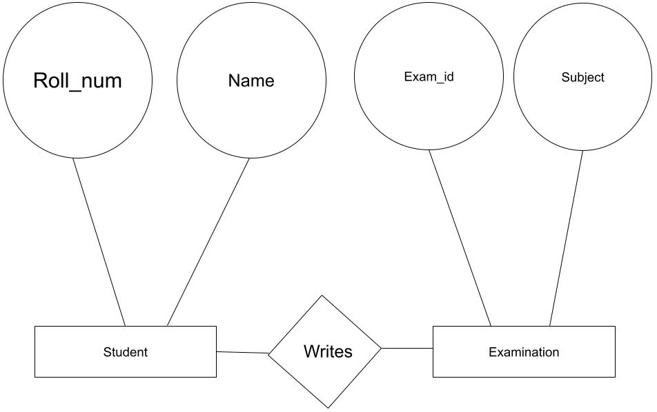
Let see the following diagram with one to many cardinality.

In the above diagram, students can write for one examination in the above diagram, but examinations can have many such students.
Therefore, the ER diagram represents three entities.
Student entity has two attributes that are roll_num and name, where roll_num is the primary key. The examination entity has two attributes, exam_id and subject, where exam_id is the primary key.
We cannot make exam_id the primary key as multiple students can write for the same exam_id.
However, we can merge students with a merge table. Minimum two tables are required for one-to-many cardinality.
Minimization in many to many cardinalities in the ER diagram
A many-to-many relation describes the relationship between many rows in a database table and many rows in a second table. Many students can write for many exams.
Let see the following diagram with many-to-many cardinality.
Look at the diagram below; the student has two attributes, roll_num, and name where roll_is the primary key.
On the other hand, the examination has two attributes, exam_id, and subject where exam _id is the primary key.
We cannot make exam_id the primary key as multiple students can write for the same exam_id.
If we try to merge it, then it will create redundant data.
Hence a minimum of two tables is required in many to many cardinalities.
Also Read - Cardinality In DBMS
FAQs
What is an ER diagram?
An Entity Relationship Diagram (ERD) represents the relationships between entities in a database. It is usually referred to as an ER Diagram.
What do you mean by cardinality in ER diagram?
Cardinality is the maximum number of ways an instance in one entity can be related to another instance. On the other hand, Ordinality is the minimum number of times an instance in one entity may be linked with an instance in another.
What is 1:1 relationship mapping?
The ONE-TO-ONE (1:1) RELATIONSHIP describes how one row in a database table relates to exactly one row in another table.
Key Takeaways
In this blog, we have learned what an ER diagram is. ER diagram represents the relationship between entities in the database.
Also, we learned about a fundamental relationship between two entities or objects called cardinality. There are three different types of relationships or cardinalities: one-to-one, one-to-many, and many-to-many. Entity-Relationship (ER) diagrams are used in databases to describe cardinality. We also talked about how cardinality is symbolized in the ER diagram.
Recommended Readings:
Visit here to learn more about different topics related to database management systems.
Also, try Coding Ninjas Studio to practice programming problems for your complete interview preparation. Ninja, don't stop here; check out the Top 100 SQL Problems to get hands-on experience with frequently asked interview questions and land your dream job.


 8+ registered

