Code360 powered by Coding Ninjas X Naukri.com. Code360 powered by Coding Ninjas X Naukri.com
Table of contents
1.
Introduction
2.
Amplitude Modulation
2.1.
Bandwidth in the AM
2.2.
Standard Bandwidth allocation for AM Radio
3.
Frequency Modulation
3.1.
Bandwidth in the FM
3.2.
Standard Bandwidth allocation for FM Radio
4.
Phase Modulation
4.1.
Bandwidth in the PM
5.
Frequently Asked Questions
5.1.
What is an analog signal?
5.2.
What is a digital signal?
5.3.
Applications of analog signal?
6.
Conclusion
Last Updated: Mar 27, 2024

Modulation

Computer Networks

Introduction

In this article, we will discuss analog to analog conversion of the signal, and we will also discuss how we can achieve this conversion. It is the analog signal's description of analog data. Analog signal modulation is the process of transforming analog signals into digital signals. It's necessary since the sender's signal is low pass and might be in the same range as the receiver's. For example, each radio station has a low pass signal with a similar range. Different stations provide different signals; each low pass signal must be moved to a different frequency band range.

For example, the government gives each radio station a certain bandwidth. Each station's analog transmission is a low-pass signal with the same frequency range. The low-pass signals must be moved to various ranges to listen to different stations.

Converting from analog to analog may be done in three ways:

  1. Amplitude Modulation (AM)
  2. Frequency Modulation (FM)
  3. Phase Modulation (PM)

Recommended Topic, Basic Networking Commands and Personal Area Network

Amplitude Modulation

The carrier signal in AM transmission is modulated such that its amplitude fluctuates with the modulating signal's shifting amplitudes. The carrier's frequency and phase remain unchanged. Only the amplitude varies in response to changes in the data. The modulating signal, the carrier signal, and the resulting AM signal are shown in the diagram below.
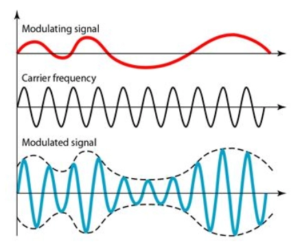
Signal

                                          Source


Modulating Signal is represented by: m(t) = Amcos(2Ï€fmt)

Carrier Signal is represented by: c(t) = Accos(2Ï€fct)

Here Am and Ac represent the amplitudes of modulating and carrier waves while fm and fc represent the frequencies of the modulating and carrier waves respectively.

Therefore modulated signal can be represented as 

M(t) = [Ac + Am cos(2Ï€fmt)] cos(2Ï€fct) 

Bandwidth in the AM

The modulation provides a bandwidth that is double the modulating signal's bandwidth and spans a frequency centered on the carrier frequency. The signal components above and below the carrier frequency, on the other hand, contain the same data. As a result, some implementations delete one-half of the signals while halving the bandwidth.

The entire bandwidth needed for AM may be calculated using the audio signal's bandwidth:

Bandwidth of AM = 2*B

Here B is the bandwidth of the message signal i.e. equal to 2*fi

Where fi represents the frequency of the message signal.

Standard Bandwidth allocation for AM Radio

An audio signal's bandwidth (for voice and music) is normally 5 kHz. As a result, an AM radio station requires a 10kHz bandwidth. In actuality, the Federal Communications Commission (FCC) authorizes each AM station to broadcast at 10 kHz.

AM stations may use carrier frequencies ranging from 530 to 1700 kHz (1.7 MHz). Each station's carrier frequency must be separated by at least 10 kHz (one AM bandwidth) from those on either side to prevent interference. If one station utilizes a carrier frequency of 1100 kHz, the carrier frequency of the following station must be at least 1110 kHz.

Also see, Message Switching in Computer Networks.

Frequency Modulation

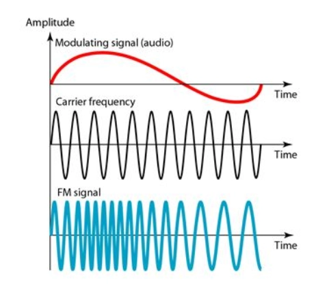
The carrier signal's frequency is modulated in FM transmission to follow the modulating signal's changing voltage level (amplitude). The carrier signal's peak amplitude and phase stay constant, but when the amplitude of the information signal increases, so does the carrier's frequency.

The modulating signal, the carrier signal, and the resulting FM signal are shown in the diagram below. 

Signal

                                     Source
 

Modulating Signal is represented by: m(t) = Am cos(2Ï€fmt)

Carrier Signal is represented by: c(t) = Ac cos(2Ï€fct)

Here Am and Ac represent the amplitudes of modulating and carrier waves while fm and fc represent the frequencies of the modulating and carrier waves respectively.

The frequency modulated signal can be represented as 

M(t) = fc + k(Am cos(2Ï€fmt))

M(t) = fc + k m(t)

Here k is proportionality constant

Am: Represents the amplitude of the modulating signal

fm: Represents the frequency of the modulating signal

fc: Represents the frequency of the carrier signal

Bandwidth in the FM

The bandwidth of an FM transmission is more difficult to determine than that of an AM signal.

Carson's Rule is a highly helpful rule used by many engineers to calculate the bandwidth of an FM signal for radio broadcast and radio communications systems. According to this rule, 98 percent of the signal power is contained within a bandwidth equal to the deviation frequency plus the modulation frequency multiplied by two. Carson's Rule is easily represented as a formula:
 

Bandwidth of FM = 2*(Δf + fm)

Δf = deviation in frequency

fm = frequency of the modulated signal

Standard Bandwidth allocation for FM Radio

Using a typical broadcast FM signal with a deviation of 75kHz and a maximum modulation frequency of 15 kHz as an example, the bandwidth of 98 percent of the power approximates to 2 (75 + 15) = 180kHz. Each station is given 200 kHz to create conveniently spaced channels.

Phase Modulation

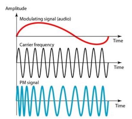
In PM transmission, the carrier signal's phase is modulated to follow the modulating signal's changing voltage level (amplitude). The carrier signal's peak amplitude and frequency stay constant, but when the amplitude of the information signal varies, so does the carrier's phase. PM is mathematically shown to be the same as FM, with one exception.

The FM's immediate carrier frequency change is proportional to the modulating signal's amplitude; whereas, in PM, the instantaneous change in the carrier frequency is proportional to the modulating signal's derivative. The modulating signal, the carrier signal, and the resulting PM signal are shown in the diagram below:
 

Signal

                                  Source


A voltage-controlled oscillator and a derivative are often used to construct PM. The derivative of the input voltage, which is the amplitude of the modulating signal, affects the oscillator's frequency.

The phase-modulated can be represented as P(t) = Accos[Wct + kpm(t)]

Ac: Represents the amplitude of carrier signal

Wc: Represents the carrier signal’s angular frequency i.e., equal to 2πfc

Kp: Represents constant of proportionality for phase modulation

m(t): Represents the modulating signal equation

Bandwidth in the PM

Although the precise bandwidth of the digital signal is difficult to calculate, it may be shown experimentally that it is many times that of the analog signal. Even though the calculation displays the same bandwidth for FM and PM.

You can also read about the network models in computer network.

Frequently Asked Questions

What is an analog signal?

Any continuous signal whose time-varying characteristic indicates another time-varying quantity, i.e., equivalent to another time-varying signal, is called an analog signal. For example, in an analog audio signal, the signal's instantaneous voltage constantly fluctuates with the pressure of the sound waves.

What is a digital signal?

A digital signal is one in which data is represented as a series of discrete numbers. A digital signal can only take on one value from a limited range of potential values at any one moment. The physical amount representing the information in digital signals may be any of the following:
→ Electric current or voltage that varies
→ An electromagnetic field's phase or polarization.
→ Pressure acoustic
→ A magnetic storage medium's magnetization

Applications of analog signal?

Analog signals are often employed in communication systems that utilize a continuous signal to transmit speech, data, image, signal, or video information.

Conclusion

This article briefly discussed how analog to analog conversion works, and we have also discussed the different ways it can be done. 

Recommended Readings:


Also check out some of the Guided Paths on topics such as Data Structure and Algorithms, Competitive Programming, Operating Systems, Computer Networks, etc. as well as some Contests, Test Series, Interview Bundles, and some Interview Experiences curated by top Industry Experts only on Coding Ninjas Studio.

Do upvote this blog and thank you for reading.

Live masterclass