Do you think IIT Guwahati certified course can help you in your career?
Introduction
Multiplexers or MUXs are devices used in electronics to select between several analog or digital inputs and send the selected input to a single output. The combinational circuit employs many input lines to select binary information and direct it to the output line.
Digital input lines, known as select lines, control the selection. There are n select lines in a multiplexer of 2^n inputs used to determine which input line goes to the output. Multiple input signals can be shared among multiple devices or resources using a multiplexer.
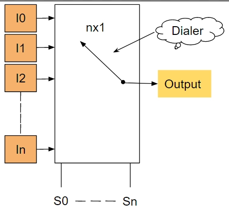
Example: You can see in the diagram given below that n number of inputs only gives one output and a dialer for selecting any one of the inputs (by moving them).
The dialer lets you choose any input. I'm sure you're wondering how this dialer chooses input. This is done with a selector variable or select line in most cases. Two selector variables are needed for this, S0 (LSB) and S1(MSB). An MSB is a bit of a data bit string's highest digit, and an LSB is a bit of its lowest digit.
Types of Multiplexers
There are various types of multiplexers which are as follows:
2x1 Multiplexer
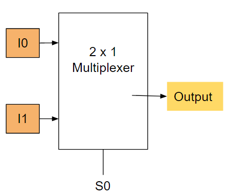
Two inputs are used in a 2x1 multiplexer, I0 and I1, one selection line, S0, and one output, O. One of these two inputs will be connected to the output based on the combination of inputs at the selection line S0.
The 2x1 multiplexer block diagram is as follows:
The Truth Table of the 2×1 multiplexer is given below.
E(Enable)
Inputs(S0)
Output(O)
0
x
0
1
0
I0
1
1
I1
If the enable is 0, the circuit will not work, and the output will be 0.
Now, if the enable is one and S0=0, then O=I0.
When S0=1, then O=I1.
The Boolean function can be determined using the truth table:
O =S0'.I0+S0.I1
The Circuit Diagram of 2x1 Multiplexer
There are two inputs in a 2 x 1 multiplexer, I0 and I1; one selects line S0 and one output O. We need 2 AND gates, 1 OR gate, and 1 NOT gate to implement a 2 x 1 multiplexer circuit.
4x1 Multiplexer
The four input lines I0, I1, I2, and I3 of a 4 x 1 multiplexer contain two data control lines, S0 and S1, with the exact physical representation of the four inputs: 2^n = 2^2 data select lines. Based on the combination of the inputs for the selection lines, one of these four inputs will be connected to the output.
The 4 x 1 multiplexer block diagram is as follows:
The Truth Table of the 4×1 multiplexer is given below.
Inputs
Outputs
S0
S1
O
0
0
I0
0
1
I1
1
0
I2
1
1
I3
The topmost AND gate will be enabled if both select inputs S0 and S1 are 0; otherwise, all other AND gates will be disabled. The data input I0 is therefore chosen for output, and it is sent through the topmost AND gate. This results in the output O = I0.
If S0 and S1 are both 1, then the bottom AND gate are enabled, and all other AND gates are disabled. This results in data input I3 being selected for transmission. This results in output O=I3.
The Boolean function can be determined using the truth table:
O=S1' S0' I0+S1' S0 I1+S1 S0' I2+S1 S0 I3
The Circuit Diagram of 4x1 multiplexer:
This 4x1 digital multiplexer has four inputs, two select lines, and one output. We need 4 AND gates, 2 NOT gates, and 1 OR gate to implement a 4x1 multiplexer circuit.
8x1 MUX
There are eight data inputs in this 8x1 Multiplexer, I0, I1, I2, I3, I4, I5, I6, and I7, and three selection lines, S0, S1, and S2, which represent 2^n = 2^3 data selection lines. Three selection lines control the selection of an input line in an 8x1 multiplexer.
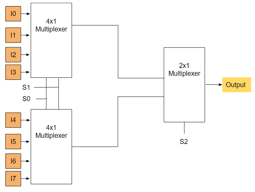
8 x 1 Mux using two 4 x 1 Mux and 2 x 1 Mux:
The below figure illustrates the flow of 8 x 1 multiplexer such that two 4 x 1 multiplexers produce the same output. Therefore we need another 2x1 Multiplexer in the second stage. All four inputs for the 4 x 1 multiplexer are initially connected in parallel, while S2 enables each Multiplexer one at a time.
The output of each 4x1 Multiplexer depends on the values of selection lines S1 & S0.
In the second stage, 2x1 Multiplexers are connected to the output of the first stage 4x1 Multiplexers.
The Truth Table of the 8×1 multiplexer is given below:
S0
S1
S2
O
0
0
0
I0
0
0
1
I1
0
1
0
I2
0
1
1
I3
1
0
0
I4
1
0
1
I5
1
1
0
I6
1
1
1
I7
S0, S1, and S2 must be equal to 0 for the topmost AND gate to be enabled, and all other AND gates must be disabled. This means that we are transmitting the input I0 as output. We will get the output I0 then.
S0 is 1 and S1 is 1, S2 is 1, and all AND gates are disabled with the exception of the bottom-most AND gate. As a result, I7 is selected as the output. The result is O=I7.
The Boolean function can be determined using the truth table:
Multiplexers with 8 data inputs, 3 select lines, and 1 output are 8 x 1 multiplexer. The circuit that can implement an 8 x 1 multiplexer needs 8 AND gates, one OR gate, and three NOT gates.
16x1 multiplexer
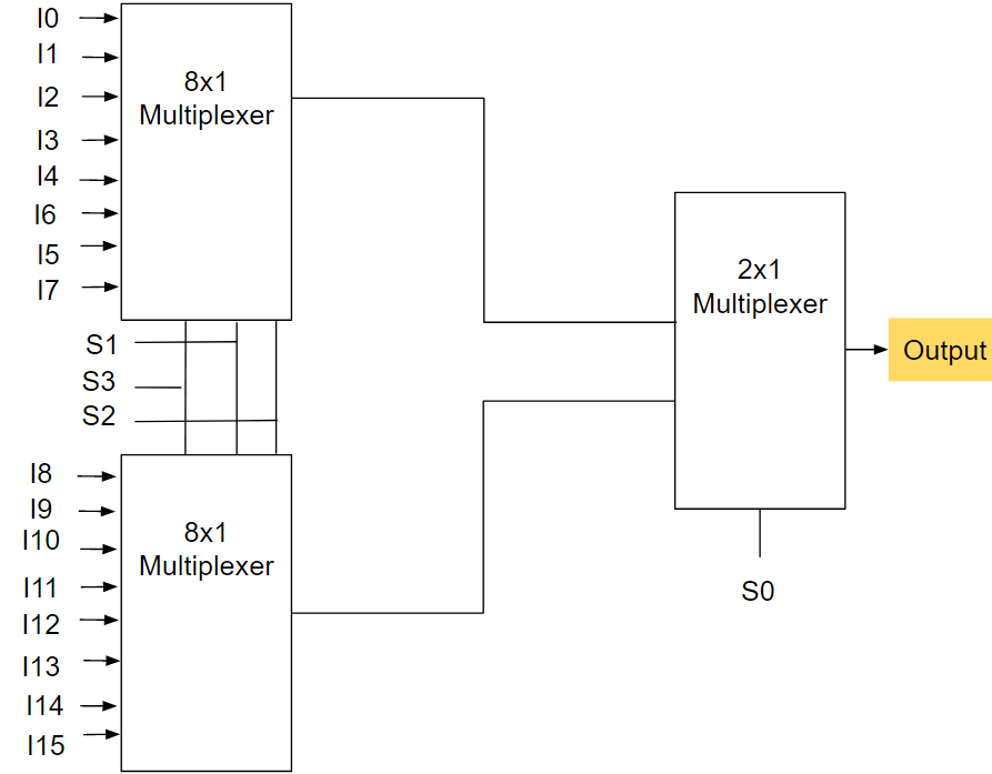
Lower order multiplexers can be used to implement higher-order multiplexers, like 8-to-1, 16-to-1, etc.
In the same way, we can implement an 8-to-1 Multiplexer by using lower order multiplexers like 8-to-1, 4-to-1, and 2-to-1. We can also implement a 16-to-1 Multiplexer.
The block diagram below shows the implementation of a 16-to-1 Multiplexer using two 8-to-1 Multiplexers and one 2-to-1 Multiplexer.
The Truth Table of the 16 × 1 multiplexer is given below:
S0
S1
S2
S3
O
0
0
0
0
I0
0
0
0
1
I1
0
0
1
0
I2
0
0
1
1
I3
0
1
0
0
I4
0
1
0
1
I5
0
1
1
0
I6
0
1
1
1
I7
1
0
0
0
I8
1
0
0
1
I9
1
0
1
0
I10
1
0
1
1
I11
1
1
0
0
I12
1
1
0
1
I13
1
1
1
0
I14
1
1
1
1
I15
The Boolean function can be determined using the truth table:
Write some advantages of a Multiplexer. Here are some advantages of a Multiplexer: Multiplexers reduce the number of wires used. Thus, the complexity and cost of the circuit are reduced. Combinational circuits can be implemented using MUX. The logic design can be simplified by using multiplexers. Multiplexers do not need k-maps or simplification.
What are the types of Multiplexing? There are two types of Multiplexing: Frequency Division Multiplexing(FDM) divides a single physical medium's bandwidth into different, independent frequency channels. Time Division Multiplexing(TDM): Unlike FDM, where a portion of the frequency band is shared across channels, TDM utilizes time to measure bandwidth. A connection lasts for a certain amount of time.
Write some applications of a Multiplexer. Some of the applications are: Multiplexers are used for multiplexing data inputs so that various types of data can be transmitted simultaneously. A multiplexer reduces the number of copper wires. Data may also be transmitted using the "GPS", "GSM" with multiplexers from a satellite to the earth.
Key Takeaways
The goal of this blog is to provide you with an overview of multiplexers (MUXs) such as 2x1, 4x1, 8x1, and 16x1, boolean expressions, logic circuits, and a few important points about them, such as how we can use lower-order multiplexers to implement higher-order multiplexers.


 8+ registered

