Table of contents
1.
Introduction
1.1.
What is Relay in IoT Development
1.2.
What do you mean by Pole and Throw?
2.
Need For Relay Modules
3.
How to use Relays with IoT Projects
3.1.
The Sainsmart 4-channel Relay Module
4.
Advantages Of Relay Modules
5.
Disadvantages Of Relays
6.
Frequently Asked Questions
6.1.
What is a four-channel relay?
6.2.
Why is the relay used in PLC?
7.
Conclusion
Last Updated: Mar 27, 2024
Medium

Relay Modules in IoT

Author Akash Nagpal
0 upvote
Career growth poll
Do you think IIT Guwahati certified course can help you in your career?

Introduction

IoT communication protocols are methods of communication that secure and maintain the highest level of security for data sent between connected devices.

The Internet of Things devices is often linked to the Internet over an IP (Internet Protocol) network. Bluetooth and RFID, on the other hand, enable IoT devices to communicate locally. There is a variation in power, range, and memory employed in these circumstances.

Connections over IP networks are more complicated, necessitating more memory and power from IoT devices, whereas range is not an issue. Non-IP networks, on the other hand, use less power and memory but have a shorter range.

In this blog, we will learn about Relay Modules, its working as well as its advantages and disadvantages in IoT development.

What is Relay in IoT Development

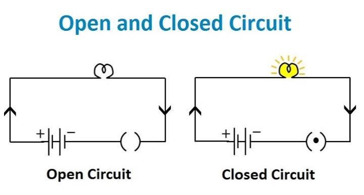
A relay is identical to a light switch on an electrical circuit. Raise the switch to turn on the light. Lower the switch to turn off the light. A light switch closes (or completes) an electrical circuit to turn on a light, and it simply opens (or breaks) the circuit to turn it off. A relay performs the same purpose as a switch, except that a low-power signal controls the switch. As seen in the two images below, different relays exist, each with its unique set of poles and throws.

What do you mean by Pole and Throw?

Pole and throw relate to how many inputs and outputs there are. Single Pole Double Throw (SPDT) relays are a frequent form of a relay. There is one incoming path and two possible outbound paths depending on the low-level incoming signal. The "usually closed" way is one of the paths; it signifies that the circuit is closed without power. The other way is "usually open," which means the circuit is open when no power is provided. Figure 3 depicts the many poles and throw options available for relays.


Image Source: Hardwarezone

Need For Relay Modules

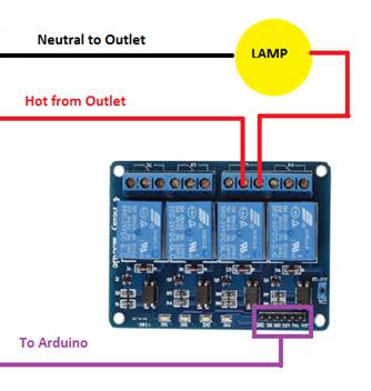
Relays are used for a simple purpose. High-powered circuits, such as lamps or lights, cannot be switched by an Arduino or Raspberry Pi. These devices usually feature 5v or 3v connectors and no additional means of switching circuits. Relays may also be used to switch existing circuitry in your home without causing too much change, such as a sprinkler system. Water sprinkler wire has previously been run to a place. Connect the solenoid valve wires to the existing power and operate your sprinklers using the relay and an Arduino. It's that easy! then switching on the light

How to use Relays with IoT Projects

Assume you wish to control a desk lamp from the cloud. To begin, you'll need an Arduino or Raspberry Pi. As previously noted, a relay is required. The first approach is to purchase all of the individual components required to build a reliable relay circuit. This would be the best option to learn everything there is to know about ideal relay circuits. The second alternative is to buy a pre-fabricated PCB board with all circuits and relays and screw-down connectors for all connections. This method is the best for prototyping with relays because nothing is permanent, and it is less costly.

The Sainsmart 4-channel Relay Module

The SainSmart 4-channel Relay Module

Image source: codeguru

The Sainsmart 4-channel Relay Module is a compact PCB board with four relays installed on it and all the necessary connections to operate the relays. This board also has an LED that shows which relays are receiving power, indicating which are switched "on."

Screw-down connectors will supply the lamp's power at the top. Figure 5 demonstrates how this relay module would operate with the light circuit. The central screw-down terminal receives hot electricity from the wall. The lamp is then connected to the "usually open" circuit. The light is connected to the neutral wall connector to complete the circuit. The Arduino would be attached to the board through the header pins on the bottom right.

Basic lamp circuit wiring diagram for the SainSmart 4-channel Relay Module

Image source: codeguru

Six header pins are necessary to control all four relays on the board. GND, IN1, IN2, IN3, IN4, and VCC are in order from left to right. Refer to the diagram given below. At least three of those connections are required to control one of the relays: GND, IN3, and VCC. The earth pin will be linked to the Arduino ground. VCC stands for positive power connection; the Arduino requires 5v. The IN3 would be linked to the Arduino pin that you're using to control the device; in this case, pin eight on the Arduino. When the Arduino code changes the pin to "HIGH," power is provided to the pin, the relay module closes the circuit, and the bulb is turned on.

Also read, What is arduino uno

Advantages Of Relay Modules

  • It enables remote control of a gadget. 0You don't have to be near the gadget to operate.
  • Changing contacts is simple.
  • Isolates the actuating part's activating section.
  • It is effective at high temperatures.
  • It is triggered with a tiny current, yet it can activate massive, powerful machinery.

Disadvantages Of Relays

  • The operation of the relay can be hampered by aged components and dust, pollution, and erroneous trips. The springs and components inside the relay deteriorate over time.
  • Relays are incapable of switching quickly. The mechanical inertia of the component limits the operation speed of a relay.
  • Continuous usage damages contacts over time (wear, oxidation, etc.)
  • They create a lot of noise with the activation and deactivation of the contacts.
  • The switching time is excessive.

Check out this article - Components Of IOT

Frequently Asked Questions

What is a four-channel relay?

The 4 Channel Relay Module is a handy board for controlling high voltage, high current loads such as motors, solenoid valves, lights, and AC loads. It's made to work with microcontrollers like Arduino, PIC, etc.

Why is the relay used in PLC?

While the PLC controls the relay, it is utilised to power the starter, switching the motor voltage. Relays, wired to produce a control sequence, can also be used for basic control systems when a PLC is too expensive.

Conclusion

In this article, we have extensively discussed Relay Modules in IoT Environment. We have also discussed working, advantages and disadvantages of Relays in IoT.

We hope this blog has helped you enhance your knowledge regarding Relays in IoT Environment. Some official documentation on big data that can help you improve your understanding is Actuators in IoT.

If you would like to learn more, check out our articles on Actuators in IoT, and Sensors and Actuators

Practice makes a man perfect. To practice and improve yourself in the interview, you can check out Top 100 SQL problemsInterview experienceCoding interview questions, and the Ultimate guide path for interviews.

Do upvote our blog to help other ninjas grow. 

Happy Coding!

Live masterclass