Do you think IIT Guwahati certified course can help you in your career?
Introduction
A UML Sequence Diagram is a visual representation of interactions between objects in a system, focusing on the order of message exchanges. It helps developers, designers, and analysts understand system behavior, communication flow, and event sequencing in software development.
What is Unified Modeling Language (UML)?
UML stands for unified modelling language. It is a standard method frequently used in Software Engineering to visualize the design of a system and represent the conceptual ideas implemented in the system.
What is a Sequence Diagram?
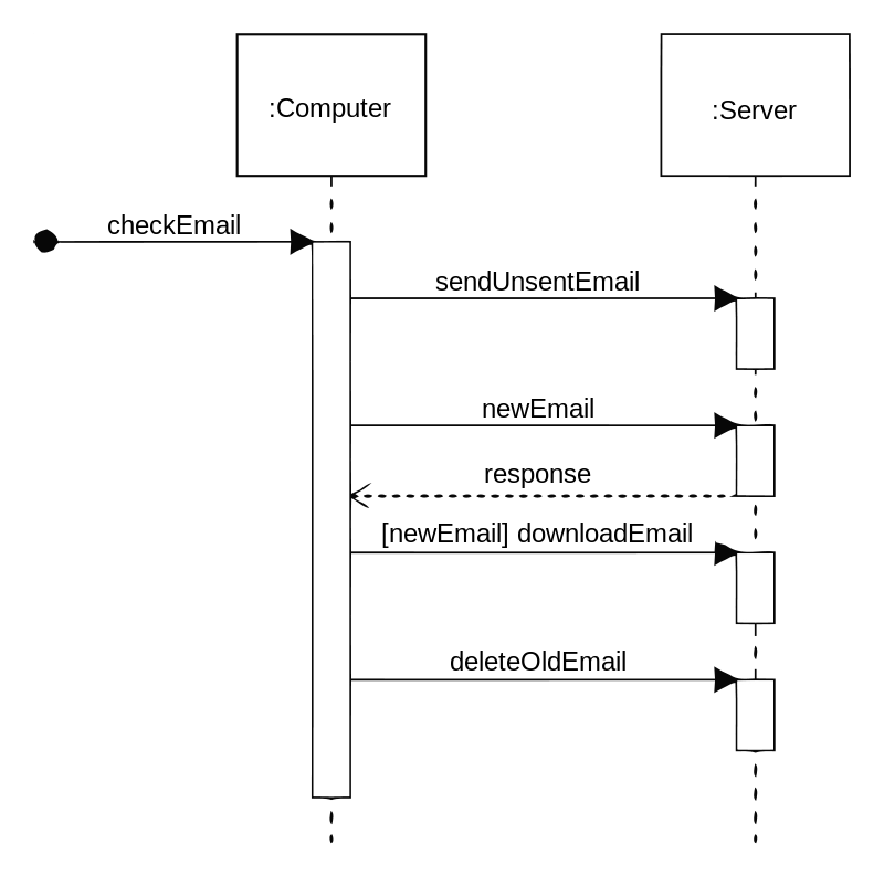
A sequence diagram is a type of interaction diagram because it represents how different objects in a system sequentially interact with each other. It consists of a group of objects (represented by lifelines) and depicts the flow of messages/interactions according to the order in which they take place.
A sequence diagram is also called an event diagram.
Example
How are UML and sequence diagrams related?
A sequence diagram is a type of interaction diagram, which in turn is one of the categories of UML.
You must be curious to know the purpose of using sequence diagrams. Let's see the various use cases in the next section.
Why Use Sequence Diagrams?
Sequence diagrams are essential in software development for visualizing object interactions over time. They offer several benefits:
Clear Communication: Helps developers, designers, and stakeholders understand system behavior and message flow.
System Behavior Representation: Shows the dynamic interactions between objects in a structured sequence.
Better Documentation: Acts as a reference for understanding system logic and design.
Error Detection: Identifies potential issues in system interactions before implementation.
Facilitates Debugging: Helps in troubleshooting by visually mapping message exchanges.
Supports Software Design: Assists in designing APIs, workflows, and event-driven processes efficiently.
Use Cases of Sequence Diagrams
Usage Scenario The diagrams representing how the system can be used is referred to as the usage scenario. It helps to cover all the possible usage scenarios of a system.
Logic of Methods Sequence diagrams can be used to visualize the logic of a method or function of a complex process that otherwise might be difficult to comprehend.
Logic of Services The services used by clients can be mapped out using a sequence diagram.
Advantages of Sequence Diagrams
Some of the advantages of sequence diagrams are as follows:
Sequence diagrams are easier to generate and maintain.
It helps to represent the message flow between the objects in an interaction.
It can be used to explore any high-level system or real-life application.
It allows for both forward engineering and reverse engineering.
It represents the details of a UML use case.
Notations in the Sequence Diagram
In this section, we will see the different notations used in sequence diagrams.
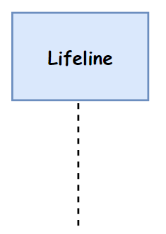
Lifeline
An individual participant in a sequence diagram is called a lifeline, and it is placed at the top in a sequence diagram.
The symbol is shown below:
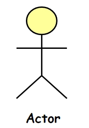
Actor
An actor represents the role of an entity while interacting with the subject. It may not always be a physical entity and can play several roles.
The symbol is shown below:
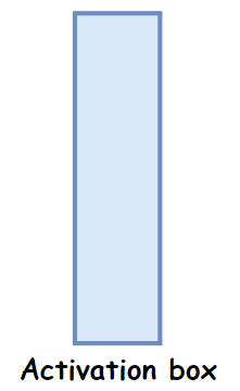
Activation
It represents the time needed by an object to complete the task and is denoted by a thin rectangle whose top and bottom are associated with the start and end times, respectively.
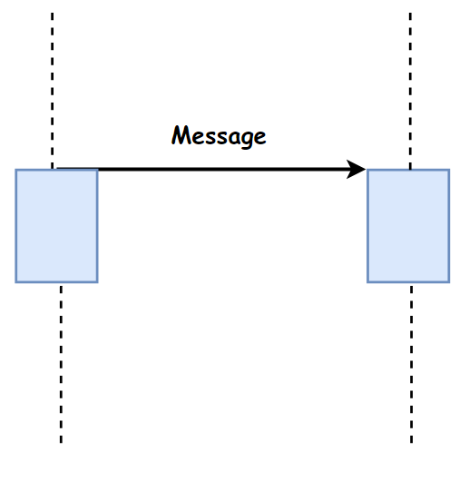
Messages
Messages are the interactions between the objects in the system and they are in sequential order. The messages are represented by arrows. The following are the different types of messages present in a sequence diagram:
Call message It represents an invocation of the operation of the target lifeline.
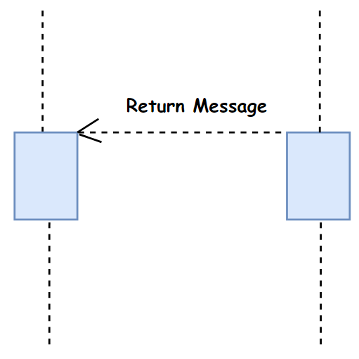
Return Message It represents the flow of messages from the receiver of the corresponding caller process.
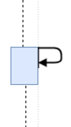
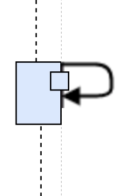
Self Message It represents the invocation of the message of the same lifeline.
Recursive Message It represents a self message which is invoked for recursive calls.
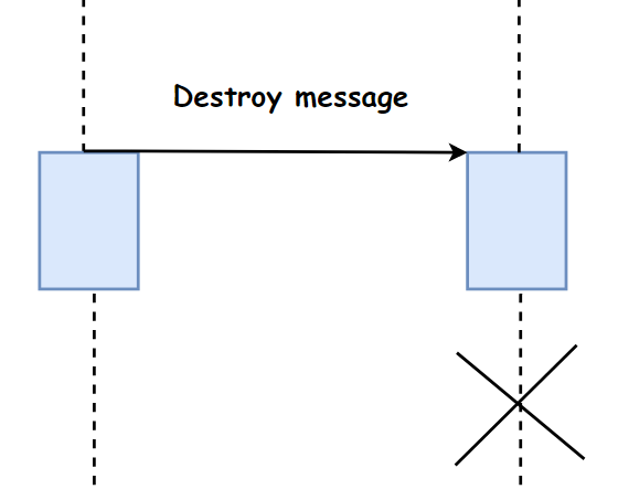
Destroy Message It represents the request of destroying the lifecycle of the target lifeline.
Duration Message It is useful for modelling a real-time system to represent the passage of time a message.
How to Generate a Sequence Diagram?
Follow these steps to create a UML Sequence Diagram:
Identify Actors and Objects: Determine the actors (users or external systems) and objects participating in the interaction.
Define the Lifelines: Represent each object or actor with a lifeline, showing their existence over time.
Establish Messages and Interactions: Use arrows to indicate messages sent between objects, specifying the type (synchronous, asynchronous, return).
Set Execution Order: Arrange messages in the order they occur, ensuring a logical flow of events.
Add Activation Bars: Highlight object activity with activation bars, showing when an object is processing a request.
Include Loops, Conditions, and Alternative Flows: Use alt, loop, and opt blocks to represent conditional flows and iterations.
Refine and Review: Ensure the diagram accurately represents the interaction logic and is free of unnecessary complexity.
Challenges of Using Sequence Diagrams
Complexity in Large Systems: Becomes difficult to manage for complex software interactions.
Time-Consuming: Requires effort to create and update when system logic changes.
Difficult to Maintain: Frequent updates in dynamic systems make maintenance challenging.
Limited Representation: Focuses only on interaction flow, lacking details about object relationships or system state.
Scalability Issues: Handling multiple objects and messages can clutter the diagram, reducing clarity.
Frequently Asked Questions
What are the three types of sequence diagrams?
The three types of sequence diagrams are Instance-level, Generic, and Specification diagrams, representing specific interactions, reusable patterns, and system behavior specifications, respectively.
Which tool is used for a sequence diagram?
Popular tools for creating sequence diagrams include Lucidchart, Microsoft Visio, PlantUML, StarUML, Draw.io, and IBM Rational Rose, supporting both manual and automated generation.
What is the dotted line in the sequence diagram?
The dotted line (lifeline) represents an object's existence during the interaction, with an activation bar indicating when it is actively processing messages.
Conclusion
UML Sequence Diagrams are essential for visualizing object interactions in a system, helping developers and stakeholders understand message flow and system behavior. They improve communication, enhance software design, and assist in debugging complex workflows.


 9+ registered