Introduction
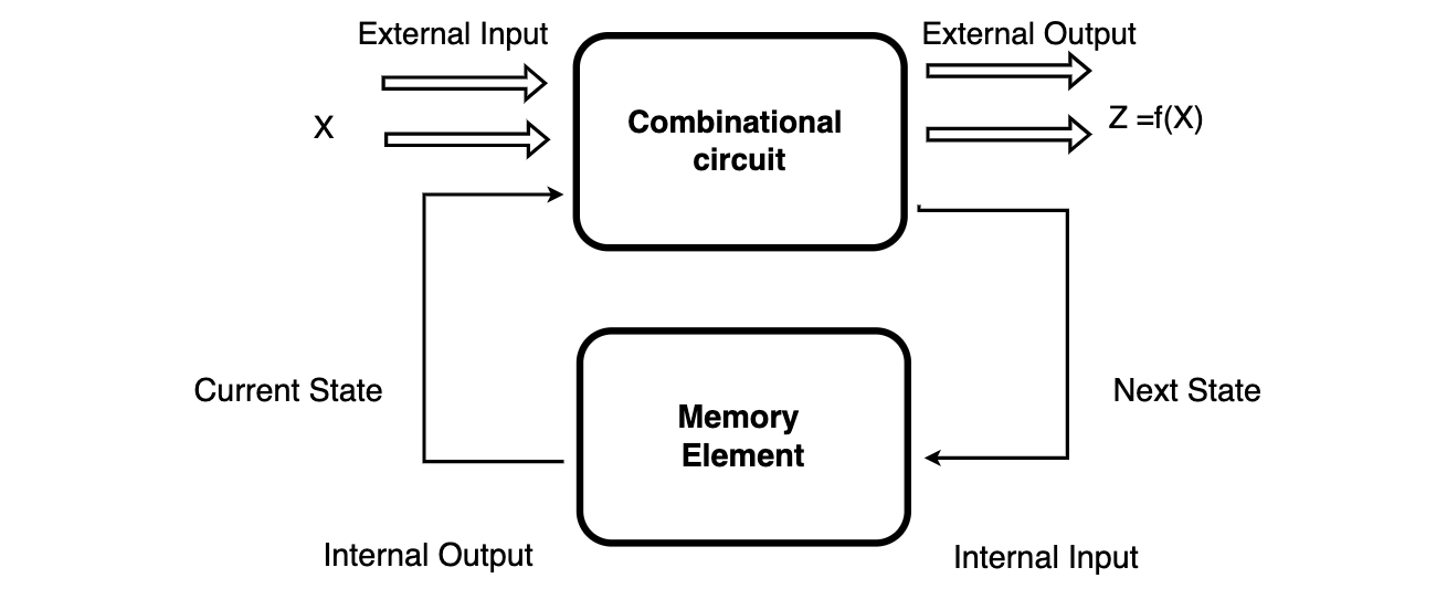
A Sequential circuit is an intelligent circuit that includes a combination of flexible inputs (X), logical gates (Computational circuit), and output volumes (Z).
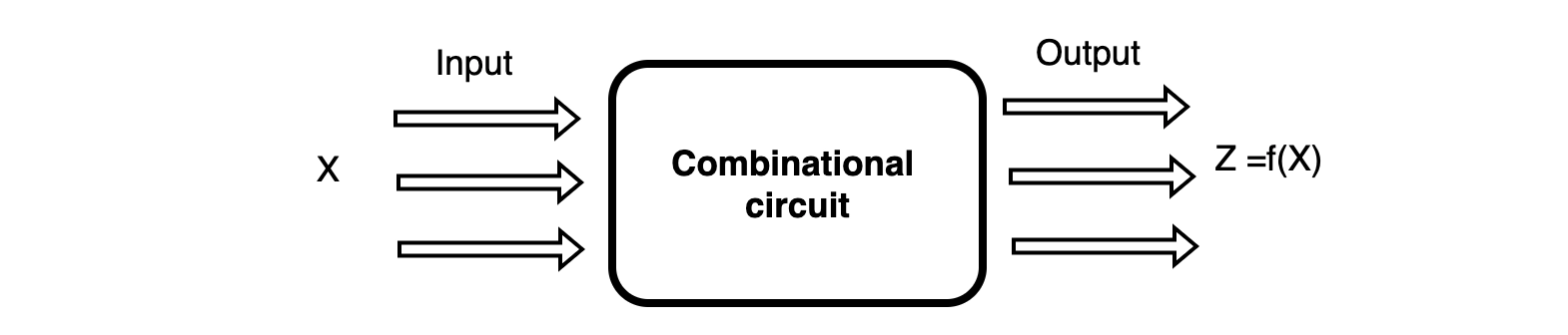
The integrated circuit produces output based on input variables only, but the Sequential circuit generates output based on the current input and previous input variables. That means consecutive circuits include memory components that can store binary information. That binary information describes the state of the consecutive circuit at that time. A latch capable of storing one piece of information.
Questions
1. A positive edge-triggered D flip-flop is connected to a positive edge-triggered J K flip-flop. The Q output of the D flip-flop is connected to both the J and K inputs of the J K flip-flop, while the Q output of the J K flip-flop is connected to the input of the D flip-flop. At first, the output of a D flip-flop is set to logic one, and the output of the JK flip-flop is cleared. Which one of the following options is the bit sequence generated at the Q output of the JK flip-flop when the flip-flops are connected to a free-running standard clock? Consider that J = K = 1 is the toggle mode and J = K = 0 is the state-holding mode of the JK flip-flop. Both the flip-flops have non-zero propagation delays.
- 0 1 1 0 1 1 0
- 0 1 0 0 1 0 0
- 0 1 1 1 0 1 1 1 0
- 0 1 1 0 0 1 1 0 0
Solution: a. 0 1 1 0 1 1 0
At first, the Q output of D - FF = 1 in starting Q output of J K - F F = 0. Now with the help of the present state and next state, the circuit.
- Toggle: J = K = 1
- Hold : J = K = 0
Make table Q output of D-FF is going to next state input of J K-F F and the bits sequence produced is like 110110…..Including initial condition (0), we get output as 0110110110. Hence answer is (A) part.
2. A four-bit Johnson counter with an initial value of (0000). The sequence of counting is:-
- ( 0, 1, 3, 7, 15, 14, 12, 8, 0 )
- ( 0, 1, 3, 5, 7, 9, 11, 13, 15, 0 )
- ( 0, 2, 4, 6, 8, 10, 12, 14, 0 )
- ( 0, 8, 12, 14, 15, 7, 3, 1, 0 )
Solution: d. ( 0, 8, 12, 14, 15, 7, 3, 1, 0 )
The 4 bit Johnson counter connects the complement of the output of the last shift register with the input of the first register with shift distance=1, i.e., 1 bit will shift/cycle. It work as follows:- 0000 //The last 0 complemented & fed as input to first register = ( 1000 1100 1110 1111 )//The last one complimented & fed as input to first register = ( 0111 0011 0001 0000).
3. The partial implementation of a two-bitt counter using the T flip-flops following the sequence 0-2-3-1-0, as shown below:-
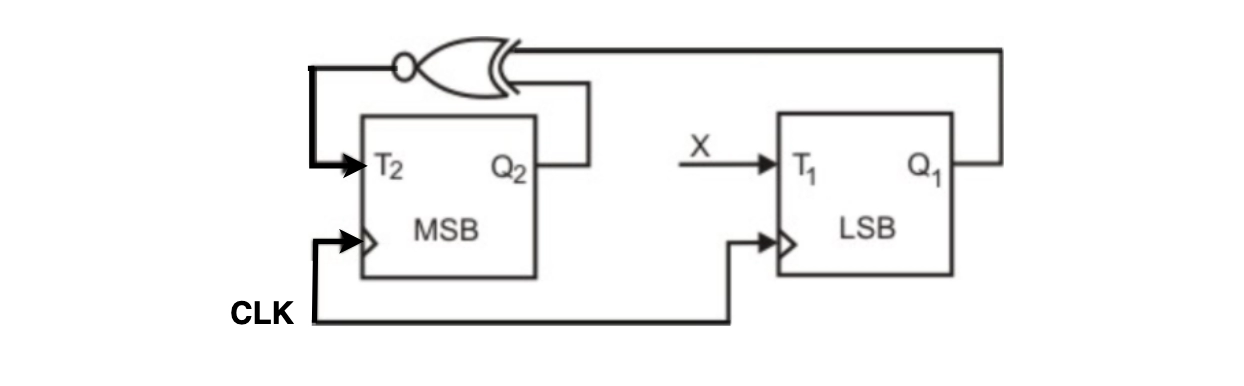
For completing the circuit, the input X should be
- Q2'
- Q2 + Q1
- (Q1 ⊕ Q2)'
- Q1 ⊕ Q2
Solution: d. Q1 ⊕ Q2
From the circuit, we see T1=XQ1'+X'Q1 ----(1), AND T2=(Q2+Q1)' ----(2) and the desired output is 00->10->11->01->00 so X should be Q1Q2'+Q1'Q2 satisfying 1 and 2.
4. The minimum number of J K flip-flops required to construct a synchronous counter with the sequence like ( 0, 0, 1, 1, 2, 2, 3, 3, 0, 0, ...) is:-
- 0
- 1
- 2
- 3
Solution: d. 3
Count sequence is 00, 00, 01, 01, 10, 10, 11, 11 the repeated sequence is above present. As two bits will not be sufficient, we need at least three flip-flops. So, the answer is 3.
5. The number of pulses is needed to change the contents of an 8-bit up-counter from 10101100 to 00100111 (the rightmost bit is the LSB)?
- 134
- 133
- 124
- 123
Solution: d. 123
8-bit Counter range from 0 to 255 To go from 10101100 (172) to 00100111 (39)
- a first counter will move from 172 to 255(255-172=83)
- 255 to 0=1 pulse
- and then 0 to 39(39-0=39).
Total=83+1+39=123 So the answer is D.
6. To design a synchronous counter having sequence ( 0-1-0-2-0-3 ) and then repeats. To implement this counter is the minimum number of J-K flip-flops required. Note: This question was asked as a Numerical Answer Type.
- 1
- 2
- 4
- 5
Solution: c. 4
Total 4. 2 J-K flip-flops for synchronous counter + 2 J-K flip-flops to make 2 bit counter. Actually, when we have repeated again, then after three, we don't know that our Synchronous counter will go to which zero. To make it work right, we need to move it to 1st zero after 3 2nd zero after 1 3rd zero after 2 i.e. 0 -> 1 -> 0 -> 2 -> 0 -> 3 (from here it again go to 1st zero). In order to decide which zero to move on, we use counters from 1 to 3; I have attached the truth table of a normal 2 bit synchronous counter using JK flip flop.
7. The following arrangement of master-slave flip flops has the initial state of P, Q as 0, 1 (respectively). After three clock cycles, the output state P, Q is (respectively),

For completing the circuit, the input X should be
- 1, 0
- 1, 1
- 0, 0
- 0,1
Solution: a. 1, 0
Given P = 0 , J = 1 and k = 1
- The initial value of P is input for the D flip-flop. So, D = 0 .Therefore, the second flip-flop output at Q is '0'. Thus, option (A) is the answer.
- JK flip-flop toggles the input in the '11' state. Therefore, the output of the first flip-flop at P is '1'.
8. Which of the following option input sequences for a cross-coupled R-S flip-flop realized with two NAND gates may lead to an oscillation?
- 11, 00
- 01, 10
- 10, 015
- 00, 11
Solution: d. 00, 11
RS flip flop using NAND gates. So, 00 input causes an indeterminate state which MAY lead to oscillation.
9. The functional difference between SR flip-flop and JK flip-flop is that
- JK Flip-flop is faster than SR flip-flop
- JK flipflop has a feedback path
- JK flip-flop accepts both inputs 1
- None of them
Solution: c. JK flip-flop accepts both inputs 1
JK flip-flop accepts both inputs as 1, but SR flip-flop doesn't.
10. A modulus -12 ring counter requires a minimum of
- Ten flip-flops
- 12 flip-flops
- Eight flip-flops
- Six flip-flops
Solution: b. 12 flip-flops
A ring counter requires 'n' flip-flops for 'n' number of states. A modulus-12 has 12 states starting from 0000 to 1011. At least 12-bits are required to design a modulus-12 counter.
11. Using RS flip flops, what will be the counter's value after giving nine pulses to its input in a three-stage counter? Assume that before giving any puls, the value of the counter is 1.
- 1
- 2
- 9
- 10
Solution: b. 2
In a three-stage counter, using RS flip flops, the value of the counter will return to the initial stage after eight pulses, and in the 9th pulse, the counter stage will exceed by 1.
Initial value of counter = 1
After 8 pulses : 1-> 2-> 3-> 4-> 5-> 6 -> 7-> 0-> 1
After 9th pulse: 1-> 2 
Option (B) is correct.
12. In an RS flip-flop, if the S line (Set line) is set high (1) and the R line is set low (0), then the state of the flip-flop is
- Set to 1
- Set to 0
- No change in state
- Forbidden
Solution: a. Set to 1
When the Set line is set high, and the Reset line is set low, then the RS flip-flop has the state set to 1.
13. Let's say k = 2^n. The output of an n-bit binary counter is fed into an n-to-2n bit decoder to create a circuit. This circuit is the same as
- A binary up counter of k bits.
- B binary down counter of k bits.
- A k-bit ring counter is written in C.
- Johnson counter D k-bit.
Solution: c. A k-bit ring counter is written in C.
For the output of a decoder, only a single output will be '1', and the remaining will be '0' simultaneously. So high output will give the count of the ring counter. Hence Ans is (C) part.
14. If both S and R inputs of an SR latch formed by cross-coupling two NAND gates are set to 0, the output is
- Q = 0, Q' = 1
- Q = 1, Q' = 0
- Q = 1, Q' = 1
- Indeterminate states
Solution: c. Q = 1, Q' = 1
We get both Q and Q' as 1 when both R and S are set to 0. This output will be permanent, and it will not be affected by the sequence in which the events occur; it will only be affected by the input values [NO RACE CONDITION]. However, if we change R=S=1 after this state, the output would be indeterminate depending on which NAND gate processes first (either Q or Q' will become 0, but we can't tell which [RACE CONDITION]), resulting in an indeterminate state.
15. The synchronous sequential circuit with one input and two outputs operates as follows: Let zk and nk represent the number of 0s and 1s in the first k bits of the input (zk + nk = k). Until one of the following conditions is met, the circuit outputs 00.
2 = zk - nk The output at the k-th clock tick and all consecutive clock ticks are 10 in this scenario.
2 = nk - zk The output at the k-th clock tick and all consecutive clock ticks is 01.
In the state transition graph of the above circuit, what is the least number of states required?
- 5
- 6
- 7
- 8
Solution: a. 5
Because we only need to count the difference between the number of 0s and 1s in the first k bits of a number, the answer must be 5. And all we have to do now is count till it hits 2 or -2 (negative when the number of 0s is less than the number of 1s). As a result, the options are -2, -1, 0, 1, and 2, which correspond to the five states of the state transition diagram. The circuit's output will be 01 for state -2, 10 for state 2 (both of these states have no outgoing transitions), and 00 for the remaining three states, according to the circuit's description.
16. Take a look at the following assertions about counters:
S1: An Overbeck counter has a Hamming distance of 1 and a Johnson counter has a Hamming distance of 2.
S2: In the Overbeck counter, only output sequences 0, 8, 12, 14, 15, 7, 3, 1, 0,... are feasible, but output sequences 2, 1, 8, 4, 2, 1,... are not.
S3: A binary counter may represent 2N states, where N is the number of bits in the code, whereas an Overbeck counter and a Johnson counter can only represent N and 2^N states, respectively.
- Only S1 and S2 are untrue, whereas S3 is correct.
- Only S2 and S3 are untrue, whereas S1 is correct.
- Only S1 and S3 are untrue, whereas S2 is correct.
- S1, S2, and S3 are all correct.
Solution: a. Only S1 and S2 are untrue, whereas S3 is correct.
The following are correct statements: S1: An Overbeck counter has a Hamming distance of 2 while a Johnson counter has a Hamming distance of 1. S2: In the Johnson counter, output sequences of 0, 8, 12, 14, 15, 7, 3, 1, 0,... are feasible, but in the Overbeck counter, output sequences of 2, 1, 8, 4, 2, 1,... are possible. S3: A binary counter may represent 2N states, where N is the number of bits in the code, but an Overbeck counter and a Johnson counter can only represent N states and 2N states, respectively.
17. A ring counter is similar to
- Toggle Switch
- Latch
- Stepping Switch
- S-R flip flop
Solution: c. Stepping Switch
A ring counter is a sort of counter made up of flip-flops coupled in a shift register, with the output of the last flip-flop fed into the input of the first, forming a "ring" structure, and the counter advances by one step for each clock pulse, similar to sequential gating systems. As a result, it functions similarly to a Stepping Switch. Option (C) is the right answer.
18. A modulo - 272 counter requires the following number of flip-flops:
- 8
- 9
- 27
- 11
Solution: b. 9
We can design a Modulo 2n counter with n flip-flops. We need a little more because 272 is greater than 256, i.e. 28; 29 = 512, which is greater than 272. In order to create a Modulo 272 counter, only 9 flip-flops are required. Option (B) is the right answer.
19. The following is the Boolean function f, which is implemented in the diagram below using two input multiplexers:

- AB’C + ABC’
- A’B’C + A’BC’
- A’BC + A’B’C’
- ABC + AB’C’
Solution: d. ABC + AB’C’
20. The following is the state table of a two-bit saturating up-counter. The counter is constructed using D flip-flops in the synchronous sequential circuit. D1 and D2 have the following values:

- D1 = Q0 + Q1 D2 = Q'0 + Q1
- D1 = Q'1Q0 D2 = Q'1 + Q'0
- D1 = Q'0 + Q1 D2 = Q0 + Q1
- None
Solution: a. D1 = Q0 + Q1 D2 = Q'0 + Q1
D1 = Q0 + Q1 D2 = Q'0 + Q1 Option (A) is accurate since D = Q.


 9+ registered