Do you think IIT Guwahati certified course can help you in your career?
Introduction
LED (Light Emitting Diode) is a widely used semiconductor which emits either visible light or invisible infrared light when forward biassed. Seven Segment Display is based on an LED display screen that displays information in the form of decimal numbers.
In this article we will briefly explore seven segments displaying their types, working, and how we can interface them with microcontrollers and their applications.
What is a seven-segment display?
A seven segment display is an LED(light emitting diode) based display that can be used to show numbers or alphabets.
It is made up of seven segments labeled as (a,b,c,d,e,f,g) which are placed in a specific pattern, where each segment represents a different part of the number.
Take a look at the image of the seven segment display below.
Typically each segment is made up of LED or LCD which can be individually turned off or turned to display a specific number.
Digital clocks, watches, calculators, and other devices that require a numeric or alphanumeric display use seven segment displays. They're also used at petrol pumps, scoreboards, and other places where numbers must be displayed.
Typically there are 2 main types of seven segment displays known as
Common Anode
Common Cathode displays.
Common Anode Displays
The cathode terminals of all LED segments are connected to logic 0 (lower voltage level) in this type of seven segment display.
To forward bias the individual LED segments at their anode terminals, logic 1 (higher voltage level) is applied via a current limiting resistor.
Common Cathode Displays
The anode terminals of all LED segments are connected to logic 1 (higher voltage level) in this type of seven segment LED display, and logic 0 (lower voltage level) is applied to the individual cathode terminals of LED segments via a current limiting resistor.
Note- Because logic circuits can sink more current than they can source, common anode seven segment LED displays are more popular than common cathode seven segment LED displays.
Applications of Seven Segment Display
Applications of seven segment displays are:
Clock Radios
Calculators
Digital watches and clocks
Microwaves
Remote Controls
Vehicle odometers
Radio Frequency Indicators
Working of Seven Segment Display
Here’s a step-by-step explanation of the working of seven segment display:
A microcontroller is used to send signals to the seven segment display commanding them to turn on or turn off specific segments. These signals are sent using pins on the display or through a separate interface.
As discussed, each segment of the display is made up of LED or LCD elements which can be turned on or off independently. If we want to display a specific number or alphabet, the corresponding segments are turned on whereas others remain off.
We can adjust the brightness of the segments by controlling the current flow through the LED or LCD elements. This is done with the help of a resistor or any other currflow-limitingting component.
To turn on a specific segment in a common anode display, we link the corresponding cathode to the ground (or a low voltage), while connecting the anode to a high voltage. The anodes in a common cathode display are connected to ground (or a low voltage), while the cathodes are connected to a high voltage.
Depending on the application, the wiring and control circuitry for a seven-segment display may differ. A dedicated clock chip, for example, may control the display in a digital clock or watch, whereas a microcontroller may control the display in a calculator or other device.
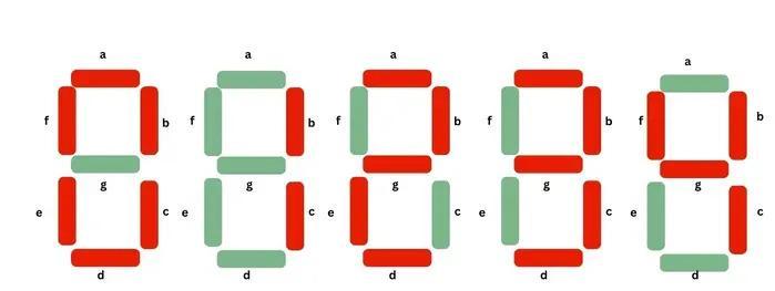
Now let us understand how different numbers are displayed by supplying power to different segments of the display.
If power is supplied to all the segments and the segment ‘g’ is disconnected then the number 0 is displayed.
If power is supplied to segments ‘b’ 7 ‘c’ then number 1 is displayed.
If power is supplied to segments ‘a’ ‘b’ ‘g’ ‘d’ ‘e’ then number 2 is displayed.
If power is supplied to segments ‘a’ ‘b’ ‘g’ ‘c’ d’ then number 3 is displayed.
If power is supplied to segments ‘b’ ‘c’ ‘f’ ‘g’ then number 4 is displayed.
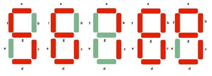
If power is supplied to segments ‘a’ ‘c’ ‘d’ ‘f’ ‘g’ then number 5 is displayed.
If power is supplied to segments ‘a’ ‘c’ ‘d’ ‘e’ ‘f’ ‘g’ then number 6 is displayed.
If power is supplied to segments ‘a’ ‘b’ ‘c’ then number 7 is displayed.
If power is supplied to all the segments then the number 8 is displayed.
If power is supplied to segments ‘a’ ‘b ‘c’ ‘d’ ‘f’ ‘g’ then number 9 is displayed.
In this way ,we can display all the decimal numbers ranging from 0 to 9.
Controlling a Seven Segment Display
Controlling a seven segment display involves sending signals to turn on or turn off specific segments to display decimal number information. Here are the steps involved in controlling a seven segment display:
First we need to determine the type of the seven segment display. The displays could be Common anode or Common cathode, according to the type of display we can determine how the segments are wired and how the display will be controlled.
Now we need to identify the pins on the display. Each segment of the display has a separate pin. In a common anode display, there are separate pins for each cathode, while in a common cathode, there are separate pins for each anode.
Depending on the display, we may need a certain voltage and current to function. The display is then powered by the appropriate power source.
Depending on the display, each segment could have multiple pins. So we connect the pins to the appropriate microcontroller or other control circuit outputs.
Write code in the appropriate programming language to send signals to turn on or off specific segments. Setting the output pins to high or low, or using specific commands to control the display, may be required.We will look at the code later in the blog.
Truth Table of Seven Segment Display
The table below shows the truth table for the seven segments to display the respective numbers. Let’s say you want to display number 1 then segments b & c will be set to true and segment code rest will be set to false.
Decimal Digits
Individual Segments Illuminated
a
b
c
d
e
f
g
0
1
1
1
1
1
1
0
1
0
1
1
0
0
0
0
2
1
1
0
1
1
0
1
3
1
1
1
1
0
0
1
4
0
1
1
0
0
1
1
5
1
0
1
1
0
1
1
6
1
0
1
1
1
1
1
7
1
1
1
0
0
0
0
8
1
1
1
1
1
1
1
9
1
1
1
1
0
1
1
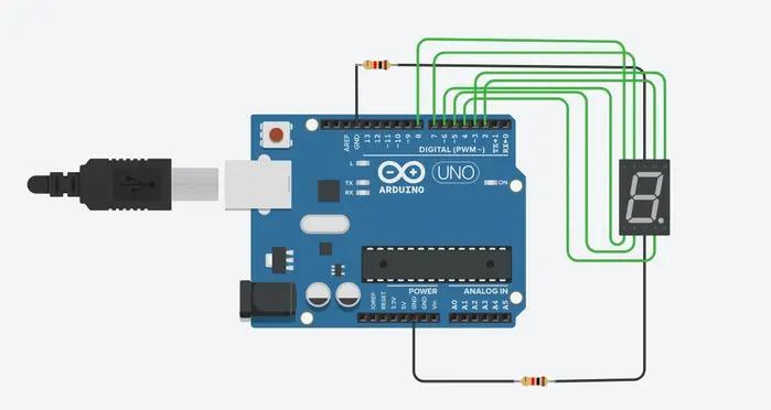
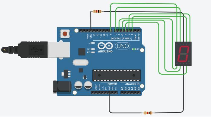
Arduino Circuit
In the below circuit we take an Arduino Uno R3 board and a Seven Segment display.
Then we will connect the corresponding labels to their pins. For example for segment ‘A’ we will connect it to pin 2. Now in similar way we can connect the rest of the segments.
Arduino Code for Seven Segment Display
The below written code is an Arduino sketch that demonstrates how to control a single-digit seven-segment LED display.
int segment_Pins[] = {2,3,4,5,6,7,8,9};

// Truth table which we saw earlier
byte segmentCode[10][8] = {

    //  a  b  c  d  e  f  g  .
    {1, 1, 1, 1, 1, 1, 0, 0},  // 0
    {0, 1, 1, 0, 0, 0, 0, 0},  // 1
    {1, 1, 0, 1, 1, 0, 1, 0},  // 2
    {1, 1, 1, 1, 0, 0, 1, 0},  // 3
    {0, 1, 1, 0, 0, 1, 1, 0},  // 4
    {1, 0, 1, 1, 0, 1, 1, 0},  // 5
    {1, 0, 1, 1, 1, 1, 1, 0},  // 6
    {1, 1, 1, 0, 0, 0, 0, 0},  // 7
    {1, 1, 1, 1, 1, 1, 1, 0},  // 8
    {1, 1, 1, 1, 0, 1, 1, 0},  // 9
};

void Display(int number) {
    for (int i = 0; i < 8; i++) {
        digitalWrite(segment_Pins[i], segmentCode[number][i]);
    }
}

void setup() {
    for (int i = 0; i < 8; i++) {
        pinMode(segment_Pins[i], OUTPUT);
    }
}

void loop() {
    for (int n = 0; n < 10; n++) {
        Display(n);
        delay(1000);
    }
}
Here's a step-by-step breakdown of what the code does:
The segment_Pins array defines the digital pins connected to each segment of the seven-segment display. The pins are listed in the order a, b, c, d, e, f, g, and the decimal point.
The segmentCode array defines the binary pattern needed to turn on each segment for the digits 0-9 and the decimal point. Each row represents a digit, and each column represents a segment. For example, the first row [ 1, 1, 1, 1, 1, 1, 0, 0 ] represents the digit 0, with all segments except the decimal point turned on.
The Display() function takes an integer argument between 0-9 and displays the corresponding digit on the seven-segment display. It does this by looping through each segment pin and setting its output value based on the binary pattern defined in segmentCode for the given digit.
In the setup function, each segment pin is initialized as an output pin using the pinMode function.
In the loop function, a for loop is used to display each digit and the decimal point in sequence.
Output:
The Display() function is called with the current digit number, and then the code waits for one second using the delay function before moving on to the next digit.
Easy to Read: Seven segment displays are simple and easy to read, even from a distance. The large and clear digits make them perfect for showing numbers in digital clocks, meters, and counters.
Low Power Consumption: These displays use very little electricity, especially when made with LED technology. This makes them ideal for battery-powered devices and energy-saving applications.
Simple Design and Control: The design and control of seven segment displays are straightforward. You only need a basic circuit to operate them, making them great for beginners and simple electronic projects.
Cost-Effective: Seven segment displays are affordable and widely available. Their low cost makes them a popular choice for mass production in electronic devices like calculators and timers.
Disadvantages of Seven Segment Displays
Limited to Numeric Display: Seven segment displays can easily show numbers but struggle with letters and complex characters. This limits their use where full text display is needed.
Poor Visibility in Bright Light: Standard seven segment displays may not be easily visible in strong lighting conditions, especially in outdoor environments without special modifications.
Fixed Size and Design: Most seven segment displays come in fixed shapes and sizes. This makes it difficult to customize them for devices that require flexible or very large displays.
Limited Aesthetic Appeal: Compared to modern graphic displays, seven segment displays look simple and outdated. They cannot create smooth curves or detailed graphics, reducing their appeal in stylish devices.
Frequently Asked Questions
What is a seven-segment display?
A seven-segment display is an LED(light emitting diode) based display that can be used to show numbers or alphabets. It is made up of seven segments labeled as (a,b,c,d,e,f,g) which are placed in a specific pattern.
What is the function of 7-segment?
A 7-segment display is basically used for numeric and limited alphanumeric characters using LEDs. The 7-segment is used Clock Radios, Calculators, Digital watches and clocks, Microwaves, Remote Controls, Vehicle odometers, and Radio Frequency Indicators
What are the different types of 7 segment?
There are 2 types known as common anode, where all the anode terminals are connected, and individual segments are lit by grounding cathode pins, and common cathode, where all cathode terminals are connected, and segments light up by applying a voltage to individual anode pins.
Conclusion
The seven segment display is a common electronic component used to display numerical and some alphabetic characters. It is simple to use, easy to read, and consumes little power, making it a popular choice in a variety of electronic devices. Different types of seven segment displays, such as common cathode and anode, dot matrix, and tri-color displays, have been developed as technology has advanced.


 9+ registered

