Do you think IIT Guwahati certified course can help you in your career?
Introduction
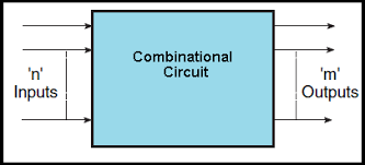
Combinational Circuits (CC) are circuits made of several logic gates: decoder, encoder, multiplexer, Demultiplexer, etc. In any electronic circuit, we have a basic block called logic gates. At a given time, the value of input tells the output of the combined circuit. The circuits do not use any memory or storage device. There are two types of combinational circuits -
Adder
Subtractor
Here in this blog, we will focus on Subtractors. For subtracting one number from another, we use subtractors. We also use 1's and 2's complement for this purpose as we are dealing with binary numbers. For basic subtraction, we have three bits which are -
Minuend (A): It is a number from which another number gets subtracted.
Subtrahend (B): It is a Number that gets subtracted.
Borrow (Bi): We get it from the last bit as input.
The outputs are -
Difference (D)
Borrow bit (Bout)
Half Subtractor
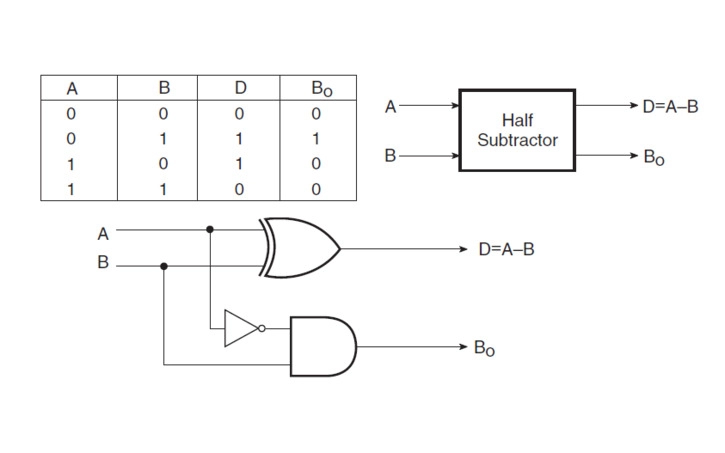
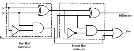
We use a half subtractor when we have to do subtraction between two bits. Also, it gives two outputs, which are the difference and borrow. In the following image, half subtractor's combinational circuit is represented with half subtractor table -
Logical expression for Half subtractor is -
D = A'B + AB' (A XOR B)
Bout = A'B
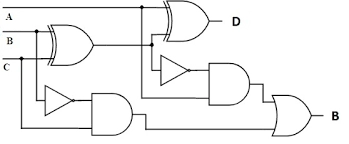
Full Subtractor
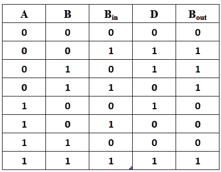
When subtracting between three bits, we use a full subtractor: the minuend, the subtrahend, and the borrow-in bits. Also, it gives two outputs, which are the difference and borrow-out. The full adder overcame the disadvantage of the Half subtractor.
Logical expression for Full Subtractor
Truth table -
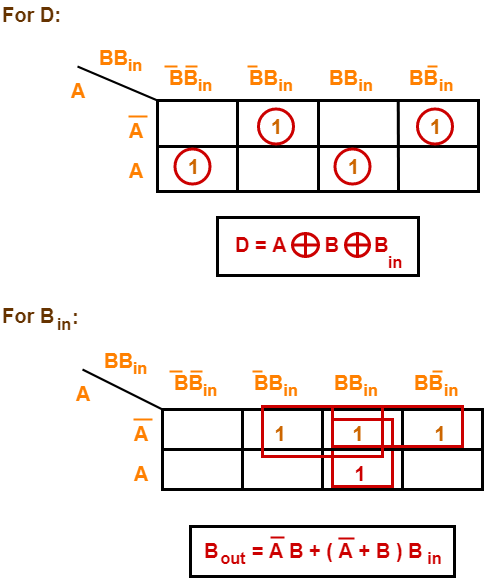
K-map for difference and borrow -
D   = A’B’Bin + A’BBin’ + AB’Bin’ + ABBin
    = Bin(A’B’ + AB)  + Bin’(AB’ + A’B)
    = Bin( A XNOR B) + Bin’(A XOR B)
    = Bin (A XOR B)’  +  Bin’(A XOR B)
    = Bin XOR (A XOR B)
    = (A XOR B) XOR Bin


Bout = A’B’Bin + A’BBin’ + A’BBin + ABBin
     = A’B’Bin +A’BBin’ + A’BBin + A’BBin + A’BBin + ABBin
     = A’Bin(B + B’) + A’B(Bin + Bin’) + BBin(A + A’)
     = A’Bin + A’B + BBin

OR

Bout = A’B’Bin + A’BBin’ + A’BBin + ABBin
     = Bin(AB + A’B’) + A’B(Bin + Bin’)
     = Bin( A XNOR B) + A’B
     = Bin (A XOR B)’ + A’B
Takes 3 inputs: minuend, subtrahend, and borrow-in.
Borrow Handling
Does not handle borrow from previous operations.
Handles borrow from previous stages.
Circuit Complexity
Simple and less complex.
More complex due to additional input and logic.
Use Case
Used for simple subtraction between two single bits.
Used when subtraction involves multiple bits and borrow handling.
Truth Table Requirement
Has a simpler truth table with fewer conditions.
Has a more detailed truth table due to borrow-in.
From the comparison, we can see that a half subtractor is ideal for simple subtraction between two bits, offering an easy and fast design. In contrast, a full subtractor is necessary when subtraction must account for a borrow from a previous stage. Although it is more complex, it plays a key role in handling multi-bit subtraction in real applications. The choice between them depends on whether borrow handling is needed in the circuit.
Parallel Subtractor
For finding arithmetic differences between two binary digits, we use a digital circuit called parallel subtractor that is greater than one bit by performing concurrent operations on appropriate pairs of bits. In several ways, we can design parallel subtractors, for example, by the combination of half and full subtractor, all full subtractor, etc.
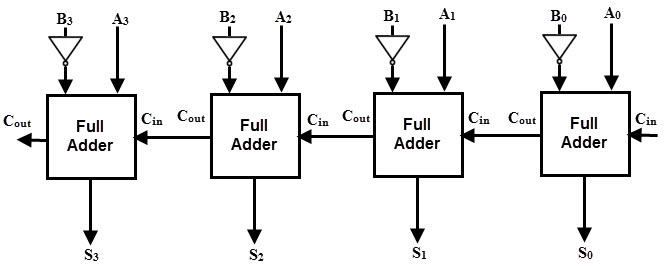
N-bit Parallel Subtractor
We can carry out the subtractor by taking the 1's or 2's complement of the number. For example, if we want to subtract A from B (A-B), we can add their 1's or 2's complement. So we can do binary subtraction with the help of a binary adder.
To obtain the 1's complement, the number subtracted is passed through the inverter first. Then to produce subtraction addition of A and 2's complement of B is done by the 4-bit adder. The result of binary subtraction A-B is represented by S3, S2, S1, S0, and output Cout is carried out, representing the result's polarity. If A > B, Cout = 0, and the result of the binary form (A-B) are in the 2's complement form; otherwise, Cout = 1 and the result is in the binary form (A-B).
Subtractors play an important role in modern digital systems. They are used for performing binary subtraction operations that are essential in mathematical calculations, digital circuit designs, and automated systems. From simple digital calculators to complex microprocessors, subtractors help in solving real-world computational problems with speed and accuracy.
In ALUs (Arithmetic Logic Units): Subtractors are a core part of ALUs in processors. They help perform arithmetic operations like subtraction, comparison, and even addition (by using complements). Without subtractors, processors would struggle to carry out basic computations needed for software and system tasks.
In Calculators and Digital Counters: Calculators use subtractors to perform quick and accurate subtraction of numbers. Digital counters, especially in timers and clocks, use subtractors to decrement values and maintain accurate counting sequences.
In Embedded and Computer Systems: Embedded systems, like controllers in washing machines or smart devices, use subtractors for decision-making processes. Computer systems also rely on subtractors for managing tasks like memory addressing and algorithm processing.
Real-Life Examples and Practice
Understanding how subtractors work in real-world examples helps strengthen practical knowledge. Practice problems and real-world examples show the real importance of half and full subtractors in solving everyday digital challenges.
Sample Problems and Solutions
Problem 1 (Half Subtractor): Subtract 1 from 0 using a half subtractor. Solution:
Subtract Borrow-in: 1 - 1 = 0 (no new borrow) Thus, output is Difference = 0, Borrow-out = 1.
Real-Life Examples
Digital Clocks: Digital clocks use subtractors to adjust time displays, especially when counting down minutes and seconds.
Automated Counters: Industrial automation systems use subtractors in counters to track and control production quantities.
Use Cases in Digital Devices
Subtractors are widely used across several digital technologies to improve processing power and efficiency.
ALUs in Microprocessors: Subtractors help perform important arithmetic and logical operations. They assist microprocessors in decision-making, mathematical computations, and handling negative numbers.
Digital Signal Processing: In DSP systems, subtractors process and modify signals. They help remove noise or unwanted signals by subtracting specific components during filtering processes.
Programmable Logic Controllers (PLCs): PLCs use subtractors in industrial settings to perform tasks like calculating differences between input signals, adjusting timers, and managing counters automatically.
Advantages and Disadvantages of Subtractors
Advantages of Using Subtractors
High Speed: Subtractors perform binary subtraction quickly, which is crucial for real-time systems and fast-processing devices.
Precision: They offer accurate results in digital calculations, ensuring that no errors occur in crucial operations.
Easy Integration: Subtractors can be easily embedded within larger circuits like ALUs and processors, supporting complex functionalities.
Supports Complex Operations: By combining subtractors with adders and comparators, systems can handle more advanced mathematical operations efficiently.
Disadvantages of Using Subtractors
Higher Power Consumption: Complex subtractor circuits can consume more energy, especially in multi-bit operations.
Increased Circuit Complexity: Full subtractors require more gates and connections, making the design and maintenance of circuits more complicated.
Scalability Issues: As the bit size increases, scaling subtractor circuits becomes harder without adding more resources and space.
Cost Factor: In large systems, implementing efficient subtractor designs can increase overall hardware costs.
Frequently Asked Questions
What is 1's complement?
We can obtain the ones' complement of a binary number's value by inverting all the bits in the number's binary representation.
What is 2's complement?
It is a mathematical operation on binary numbers. It is an example of a radix complement. An N-bit number's two's complement is defined as its complement concerning 2^N; the sum of a number and its two's complement equals 2^N.
What are the advantages of using combinational circuits?
Here the present input decides the output. Fast speed Time independent Easy to use as designed well with fundamental building blocks: logic gates
What is the advantage of a parallel subtractor?
All bits are subtracted simultaneously, which means output is provided at the same time. For the same reason, it is faster also less costly.
What is the disadvantage of a parallel subtractor?
Each adder must wait for the carry to be created by the preceding adder in the chain.
Conclusion
Subtractors are key elements in digital electronics, helping perform binary subtraction efficiently. We covered Half Subtractors, Full Subtractors, and N-bit Parallel Subtractors, each suited for different needs. They are widely used in ALUs, calculators, and embedded systems. Understanding subtractors builds a strong foundation for learning computer architecture and hardware design. For learners and professionals, mastering these basic building blocks is essential for creating more advanced digital solutions.


 9+ registered

