Do you think IIT Guwahati certified course can help you in your career?
Introduction
Flip-flops continue to maintain their state until they are triggered by an input pulse. A trigger causes the flip-flop outputs to change state in accordance with defined rules and remain in those states until the next trigger. A flip-flop circuit can have several different types of designators, including T Flip flop, SR Flip Flop, JK Flip Flop, and D Flip Flop. Let's discuss the T Flip Flop in this blog.
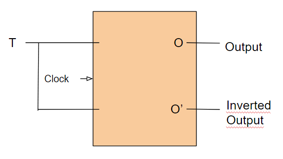
What is T Flip Flop?
Its defining characteristic is its ability to change its output state. The T Flip-Flop is a synchronous device. You switch from one state (high) to the other state (low) when you toggle.
T flip-flops are edge-triggered devices. It is also named toggle flip flop because of its toggling capability. JK flip-flops are modified versions of this device. When we connect J and K inputs, we create a T input. That's why a T flip flop is also known as a JK flip flop with a single input.
Construction of T Flip Flop
T flip-flops can be constructed the simplest of all with a JK flip-flop. It consists of two inputs, J and K, connected. The logic circuit of a T flip–flop is given below:
We can design a T Flip Flop with the help of three methods:
SR Flip-Flop
D Flip-Flop
JK Flip-Flop
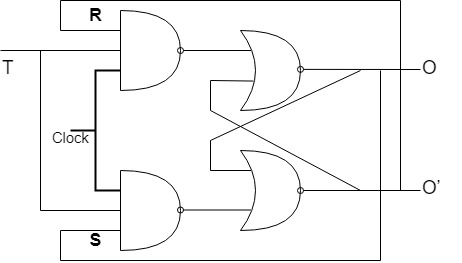
Using SR Flip-Flop
You can construct it by feeding AND gates to NOR gates SR latches. In each AND gate, the input is fed back with the output.
To make this work, connect S to the output of a two-input AND gate, which is provided by input T. The R input should now be connected to the output of a two-input AND gate which is provided by T input.
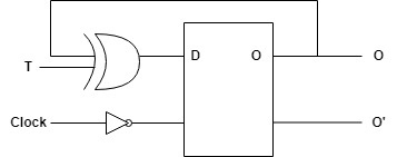
Using D Flip-Flop
The previous state of O is the XOR with the input T. Next state of O is given at the input D.
The state will remain the same when T=0, D=O at every positive edge.
T=1, D=O, and both remain unchanged during the positive edge clock.
At T=0, the state is retained, but when T=1, it is toggled.
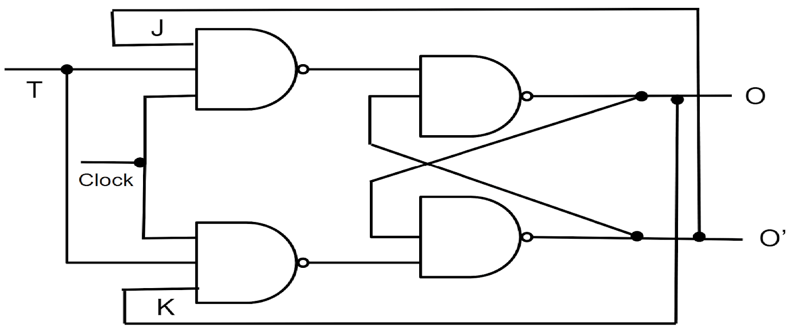
Using JK Flip Flop
As shown below, we can create a logic circuit for a single bit toggle flip-flop by connecting the J and K data inputs. The common point at the connection point between the two inputs is named T.
Truth Table of T flip flop
Truth tables illustrate how an output of a logic circuit responds to varying combinations of inputs. It is necessary to set the clock signal high to toggle the output. No matter how high or low the input signal is, the output remains the same when the clock is set low. The clock signal must be high to change the output condition.
Here is the truth table for the T Flip flop in reference to the JK flip flop.
Clock
T
O(n+1)
0(↓)
x
On
Memory
1(↑)
0
On
Memory
1(↑)
1
O’
Toggle
Case 1: Now, if the clock is low(0), then the flip flop will not function, which is why the state will be stored, which means that whatever the value of T, our output will be On(memory).
Case 2: As long as the clock is set to high(1), then J in this scenario will be 0, and K will be 0 as well, so the output will be On whenever this occurs.
Case 3: A toggle action will happen when the clock is high(1) and J = 1, K = 1, which is the case when the clock is high(1) and J = 1, K = 1.
Characteristic Table of T Flip Flop
The Characteristics Table identifies the next state of the flip-flop given the current state and input. Characteristic table can only be derived from the truth table:
On
T
O(n+1)
0
0
0
0
1
1
1
0
1
1
1
0
In this, there is a single output, i.e., O(n+1)(next state), which is dependent upon the On(present state) as well as the input. A single output is generated, called O(n+1)(next state), which is determined by inputs and the present state.
So we have concluded that:
O(n+1) = T’O + TO’
O(n+1) = T XOR O
O(n+1) = T ⊕ O
Excitation Table of T Flip Flop
An Excitation Table defines flip-flop input variables based on the current and next states. Excitation table can only be calculated if you have the characteristic table.
On
O(n+1)
T
0
0
0
0
1
1
1
0
1
1
1
0
The excitation input T = 0 is required for the state transition from On = 0 to O(n+1) = 0.
When On = 0 and On+1 = 1, the input required for excitation is T = 1.
For input T = 1, the state transit from On = 1 to O(n+1) = 0.
When T=0, the state transition is from On = 1 to O(n+1) = 1.FAQ’s
Counters T Flip Flops are widely used in binary counters. They toggle their state on each clock pulse, making them ideal for counting operations in digital clocks, frequency counters, and event counters.
Data Storage T Flip Flops can store a single bit of data and maintain it until a change is triggered. This feature makes them useful in memory elements and simple data-holding circuits within digital systems.
Synchronous Logic Circuits In synchronous logic systems, T Flip Flops help manage state transitions based on clock signals. They ensure all parts of the circuit change state in a coordinated manner, improving timing and reliability.
Frequency Division A T Flip Flop toggles its output on each clock cycle, effectively dividing the frequency of the input signal by two. Cascading multiple T Flip Flops results in further frequency division, which is useful in timing circuits.
Shift Registers T Flip Flops are used in shift registers for bit-level data manipulation. They help in shifting data left or right upon clock pulses, useful in serial-to-parallel and parallel-to-serial data conversion.
Advantages of T Flip Flop
Simplified Design for Toggling The toggling nature of T Flip Flops simplifies the design of circuits where frequent state changes are needed, reducing the complexity of control logic in counters and frequency dividers.
Efficient Frequency Division Their ability to divide frequency makes them efficient components in clock generation circuits, where accurate timing signals are necessary for the proper functioning of digital systems.
Reduced Component Count T Flip Flops can sometimes replace more complex flip flops in specific scenarios, minimizing the number of logic gates and components required in a digital design.
Reliable State Control With only one input (T), the T Flip Flop reduces input complexity and ensures reliable toggling behavior, which is beneficial for deterministic control in synchronous circuits.
Cost-Effective for Specific Applications In applications like binary counters or frequency dividers, using T Flip Flops can reduce both cost and power consumption compared to using other types of flip flops.
Disadvantages of T Flip Flop
Limited Functionality T Flip Flops are less versatile compared to D or JK Flip Flops. They are primarily suitable for toggling, making them less useful in applications requiring set/reset or direct input/output control.
Not Suitable for Asynchronous Circuits T Flip Flops depend on clock signals for toggling. In asynchronous systems where timing is not uniform, they may not function correctly, leading to unpredictable behavior.
Prone to Race Conditions If not properly synchronized in sequential circuits, T Flip Flops can be susceptible to race conditions, potentially causing glitches or incorrect state transitions.
Hard to Implement Complex Logic When a design requires multiple input conditions or data manipulation, T Flip Flops are harder to configure than more flexible flip flops like JK or D types, reducing their usability in complex logic designs.
Frequently Asked Questions
Write some applications of T Flip Flop.
Some applications are: → In addition to their use in binary counters, they are also used in shift registers. → These circuits divide the frequency of periodic waveforms. → A Flip-Flop can be used as a digital counter, counting pulses or events.
What are the advantages and disadvantages of T Flip Flop?
Here are the advantages and disadvantages: Advantage: It has two inputs toggle and a clock input. They are good for counters because the values get complimented when the clock is triggered. Disadvantage: The state can only be determined if the previous state is known and devices are not available as integrated circuits.
What is the difference between JK flip-flop and T flip-flop?
When both inputs are set to 1, the JK flip flop functions as a T-type toggle flip flop. Clocked JK flip flops are an improvement upon SR flip flops. Despite this, their "race" problem still exists. A timing pulse is deactivated before the output Q changes its state.
Conclusion
This blog has given us a general overview of T Flip Flop. In this lesson, we learned how to design a T Flip Flop by combining SR Flip Flop, D Flip Flop, and JK Flip Flop. Following that, we saw the truth table, characteristic table, and excitation table for this T Flip Flop. Thank you for reading, and I hope you find this helpful.


 8+ registered

