Table of contents
1.
Introduction
2.
UART Connections
3.
Working of UART
3.1.
Start Bit
3.2.
Data Frame
3.3.
Parity Bit
3.4.
Stop Bit
4.
Steps of UART Transmission
5.
Advantages of UART
6.
Disadvantages of UART
7.
Frequently Asked Questions
7.1.
What does UART stand for?
7.2.
What is the maximum length of the UART data frame?
7.3.
What is the optimal baud rate of UART?
8.
Conclusion
Last Updated: Mar 27, 2024
Easy

UART interface in IoT

Author vishal teotia
1 upvote
Career growth poll
Do you think IIT Guwahati certified course can help you in your career?

Introduction

A UART (Universal Asynchronous Receiver/Transmitter) is a hardware device designed for asynchronous communication. This is not a communication protocol like SPI or I2C but a physical circuit. In this case, you can configure the data format and transmission speed. It is one of the most used device-to-device communication protocols.

UART can be configured to work with many different types of serial protocols that involve sending and receiving serial data. Serial communication uses only one line or wire to transfer data bit by bit. Serial data transfer over two wires is possible in two-way communication. Serial communications may require less circuitry and wires depending on the application and system requirements, which reduces the implementation cost.

UART is mainly used by embedded systems, microcontrollers, and computers as a device-to-device hardware communication protocol. In contrast to the other communication protocols, UART uses only two wires for transmission and reception.

Functions of the UART:

  • For outbound communications, it transforms parallel data into serial data.
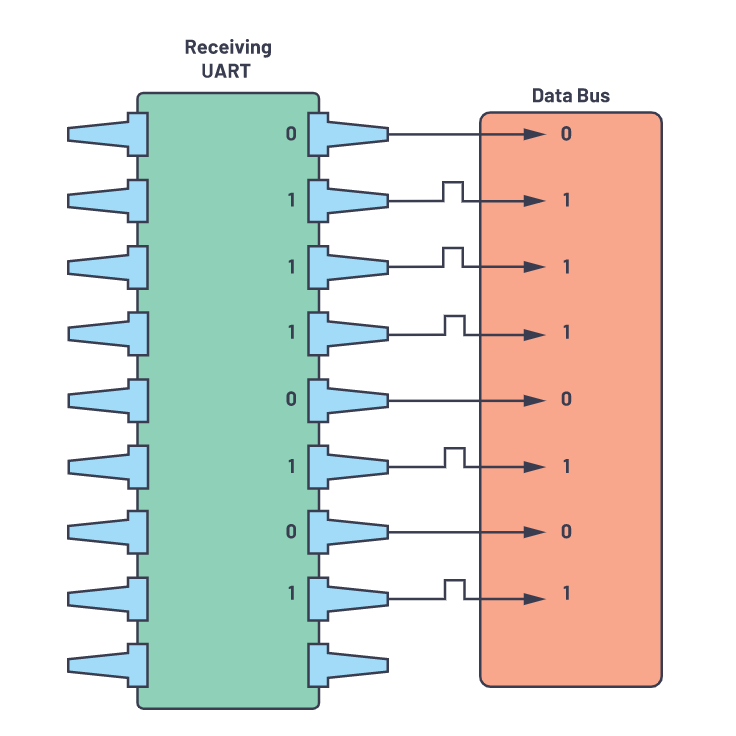
  • For inbound communications, it transforms serial data into parallel data.
  • The parity bit is added to outgoing transmissions, and the parity bit is checked for inbound transmissions.
  • Manages to interrupt requests and device management, involving synchronizing the operating speed of the computer and the device.

UART Connections

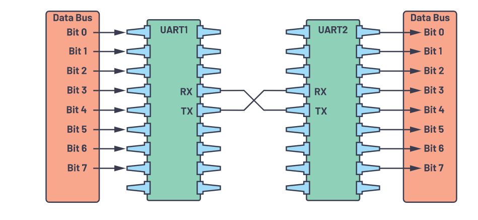
A serial format is used to transmit data. There are only two pins/terminals/ports, one for receiving and another for transmission. Receiving pins are denoted by Rx, while transmitting pins are denoted by Tx.

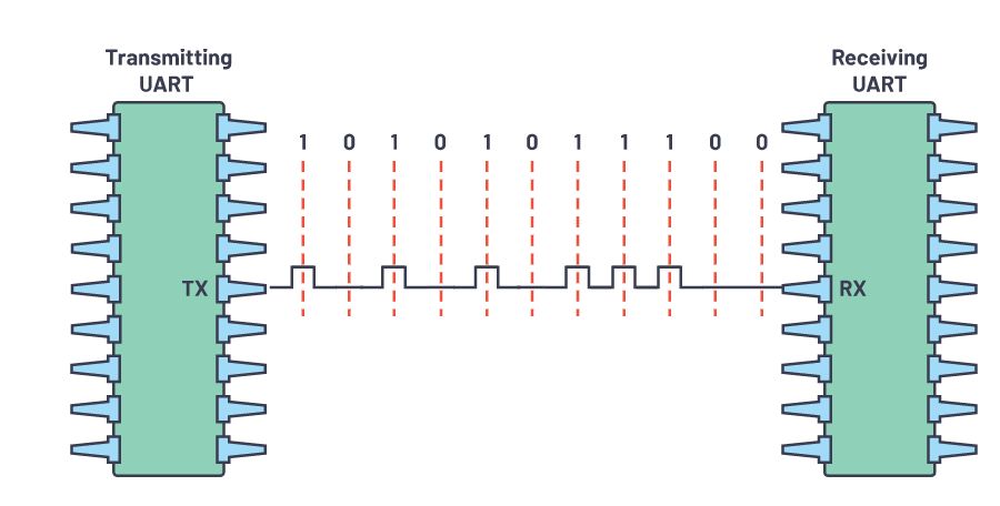
The figure below illustrates how two UART devices communicate directly with each other. A Tx from the first device is connected to an Rx from the second device, and vice versa.

                                                                           UART Connections

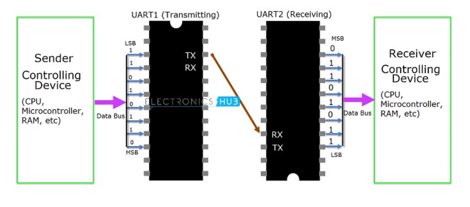
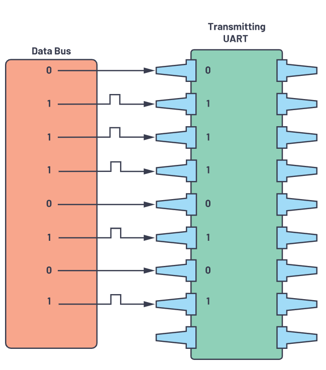
Data is sent parallel to the transmitting UART by a controlling data bus. Data will now be transmitted serially, bit by bit, over the transmission line (wire) to the UART that will receive it. In turn, this will convert the serial data into parallel for the receiving device.

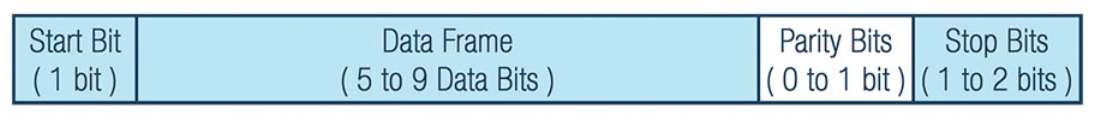
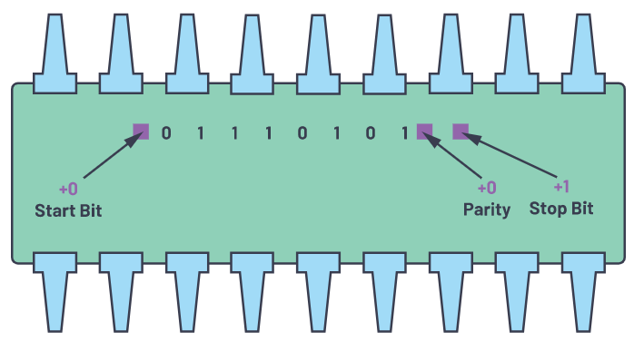
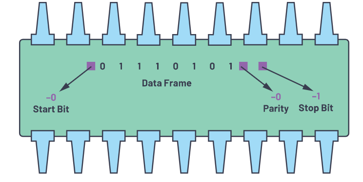
Asynchronous means there are no clock signals; instead, it employs start and stop bits to signal the beginning and ending of each data packet. By reading these bits, a receiving UART device knows when to begin reading data packets and when to stop reading them. 

Maintaining the baud rate is crucial. A Baud rate is simply the number of bits transferred in a second, expressed in bits per second. All UARTs must have baud rates within 10% of each other.

Also see, Difference Between Verilog and Vhdl

Working of UART

The peripherals that use UART for data transmission send their data in parallel. E.g., if a microcontroller wants to communicate with another peripheral using UART, it must first send data to the UART in parallel format.

UART devices collect all data and convert it to a serial format. To create a complete data packet, they add the start bit, parity bit, and stop bit.

                                                                                  UART Working

These data packets are sent by the transmitter (Tx) to the receiver (Rx). This data packet is accepted by the receiving UART device, which removes all extra bits such as the stop bit, start bit, and a parity bit. Then it converts the received serial data packet into the parallel format and sends it further to the targeted peripheral.

Start Bit

The ideal UART data transmission line (Tx) state is logical high (meaning there is a high pulse). In order to start transmission, the sender UART sets the TX line to low (which means it sends a low pulse to the receiver RX), indicating that transmission has begun. As soon as the receiving UART receives a low signal/pulse, it gets ready to receive data from the transmitter.

Data Frame

The data being transferred is contained in this part. A data frame can have a length of up to 9 bits when the parity bit is not set or absent but is usually between 5 and 8 bits with the parity bit included. In many cases, the least significant bit (LSB) is transmitted first.

Parity Bit

The receiver checks whether the data received is correct or not with this single bit field. This is an optional bit. This field has odd parity and even parity. It is added as LSB in the original data.

Odd parity: When the total number of 1's (high bits) in the data frame is odd, then the parity bit is set to 0, indicating odd parity.

Even parity: If the number of 1s in the data frame is an even number, then the parity bit will be set to 1, indicating even parity.  

Stop Bit

This bit indicates the end of the data packet. The transmitter sets the Tx (Transmission line) line in the ideal state, i.e., in high state (High pulse), to indicate the end of transmission.

                                                                             UART Packet

Steps of UART Transmission

First: Parallel data is received by the transmitting UART from the data bus.

                                                                  Data bus to the transmitting UART

Second: A transmission UART will add the start bit, parity bit, and stop bit(s) to a data frame.

                                                                        Transmitting UART

Third: Serially, the packet is sent from the transmitting UART to the receiving UART from start bit to stop bit. Data is sampled on the receiving UART at the preconfigured baud rate.

                                                                           UART transmission

Fourth: Start, parity, and stop bits are discarded by the receiving UART.

                                                                            Receiving UART

Fifth: Receiving UARTs convert serial data back into parallel and send it to the data bus.

                                                                       Receiving UART to the data bus

Advantages of UART

  • It is bidirectional.
  • It is a full-duplex.
  • There is no clock signal because it is asynchronous.
  • Error checking using parity bit.
  • Data format and transmission speeds are configurable.
  • As long as both sides are set up for it, the structure of the data packet can be changed.

Disadvantages of UART

  • The length of the data packet is limited to a maximum of 9 bits.
  • The baud rates of every UART must be within 10% of each other.
  • It does not support multiple slaves or masters therefore there are no multiple senders or receivers.

Frequently Asked Questions

What does UART stand for?

It stands for Universal Asynchronous Receiver/Transmitter.

What is the maximum length of the UART data frame?

The maximum length of the data frame can go up to 9 bits.

What is the optimal baud rate of UART?

The baud rates of every UART must be within 10% of each other.

Conclusion

A UART is an essential protocol for both designers and makers. The UART communication protocol is straightforward and easy to use and designed for beginners. After learning it, you can move on to coding for other protocols like I2C and SPI. In this article, we have discussed UART protocol and its usage.

Recommended Read: 

What is arduino uno

Check out this link if you want to learn the basics of the Internet of Things(IoT).

If you are preparing for the upcoming Campus Placements, don't worry. Coding Ninjas has your back. Visit this data structure link for cracking the best product companies.

Live masterclass