Do you think IIT Guwahati certified course can help you in your career?
Introduction
The Unified Modeling Language is a modeling language that can be used for any purpose. The main goal of UML is to establish a standard for visualizing the design of the system. It looks a lot like designs in other branches of engineering.
Unified Modeling Language is a visual language rather than a programming language. Unified Modeling Language diagrams are used to depict a system's behavior and structure. UML is a modeling, design, and analysis tool for Software Engineers, entrepreneurs, business people and system architects. UML was approved as a standard by the OMG(Object Management Group) in 1997. Since then, the OMG has been in charge of it. In 2005, the ISO(International Organization for Standardization) accepted UML as a standard. Unified Modeling Language has been updated throughout time and is examined on a regular basis.
The Need for UML
Complex applications involve the collaboration and planning of various teams, requiring a clear and straightforward method of communication between them.
Code is not understood by people in businesses. As a result, Unified Modeling Language becomes critical for communicating the system's core requirements, features, and procedures to non-programmers.
When teams can view processes, user interactions, and the system's static structure, they save a lot of time in the long run.
UML Architecture
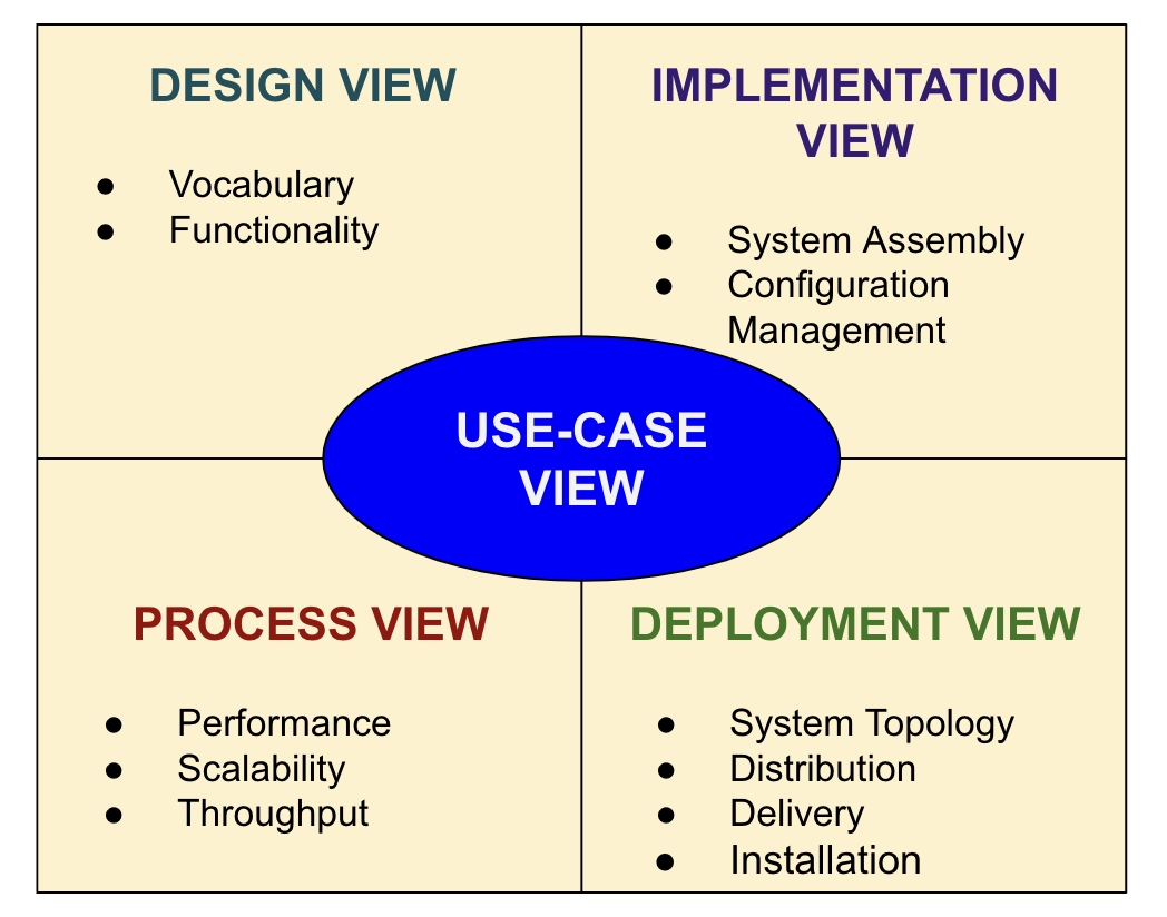
Software architecture refers to how a software system is constructed at its most fundamental level. It is necessary to think big from a variety of angles while keeping quality and design in mind.
The software team is responsible for a variety of practical concerns, including:
The development team's structure.
The company's requirements.
The development cycle.
The structure's original intent.
The basic design of a comprehensive software system is provided by software architecture. It specifies the parts that make up the system, their functions, and how they interact with one another. In a nutshell, it's a large picture or overall structure of the entire system, showing how everything interacts.
Software developers, project managers, clients, and end-users can all benefit from the software architecture. Each will bring distinct agendas to a project and will have various perspectives on the system. It also includes a compilation of different perspectives. It's best described as a compilation of five points of view:
Things, relationships, and diagrams are the three main building blocks of UML. By rotating multiple different blocks, building blocks create one full UML model diagram. It is crucial in the creation of UML diagrams.
The following are the basic UML building blocks:
Things
Relationships
Diagrams
Things
Things refer to anything that is a physical entity or object. It can be broken down into various categories:
Structural Things
Behavioral Things
Grouping Things
Annotational Things
Relationships
It shows how things are connected in meaningful ways. It depicts the relationships between entities and defines an application's functionality. Relationships can be divided into four categories:
Dependency
Association
Generalization
Realization
Diagrams
The diagrams are the visual representations of the models, which include symbols and text. In the context of the UML diagram, each symbol has a different meaning.
UML diagrams can be divided into three groups, as shown below:
Structural Diagram
Behavioral Diagram
Interaction Diagram
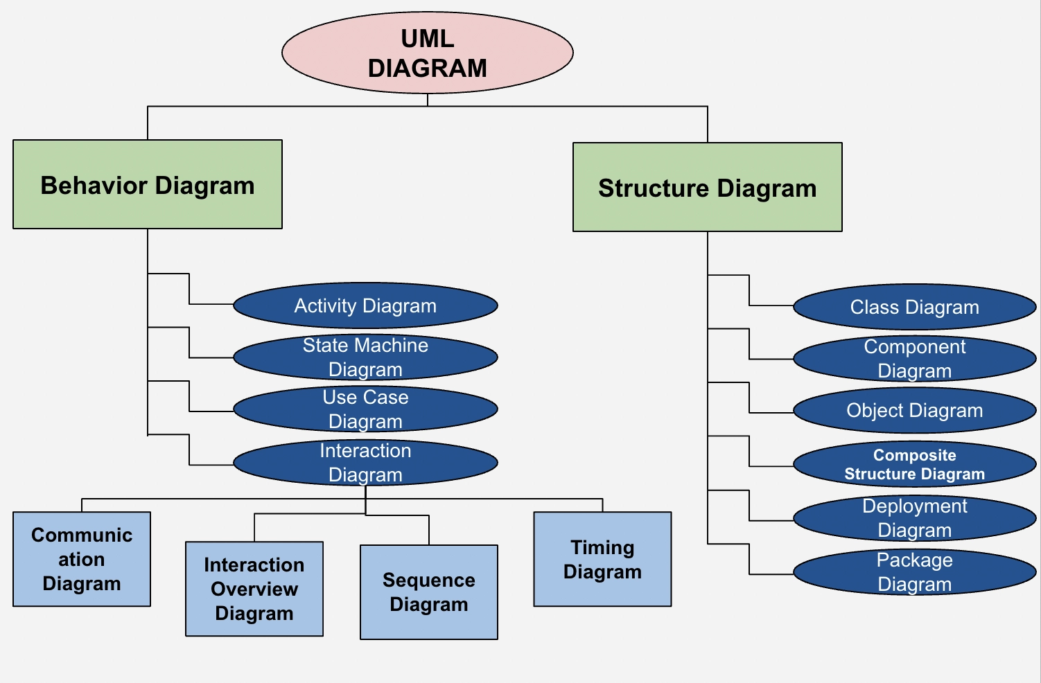
UML Diagrams
Object-oriented design and analysis are linked to Unified Modeling Language. Structural, behavioral, and interaction diagrams are the three types of UML diagrams. In the diagram below, the representations are arranged in a hierarchical order:
UML creates diagrams by combining elements and forming associations between them.
UML diagrams are divided into three categories:
Structural Diagrams
It depicts a system's structure and represents a system's static view. It displays several objects that can be found in the system.
The structural schematics follow:
Component Diagrams
Object Diagrams
Class Diagrams
Composite Structure Diagrams
Package Diagrams
Deployment Diagrams
Behavioral Diagrams
It depicts a system's behavioral characteristics. It is concerned with the system's dynamic components. The following diagrams are included:
Use Case Diagrams
State Machine Diagrams
Activity Diagrams
Interaction Diagrams
It's a subset of behavioral diagrams. It displays the data flow between two objects and their interaction. The following are some UML interaction diagrams:
Sequence Diagrams
Timing Diagrams
Communication Diagrams
Interaction Overview Diagrams
Use of Object-Oriented Concepts in UML
UML is the next generation of object-oriented(OO) analysis and design.
Data and methods that control the data are both contained in an object. The data represents the object's current status. A class is a type of object with a hierarchy to model a real-world system. The hierarchy is represented by inheritance, and the classes can be linked in various ways depending on the situation.
Objects are real-world entities that occur all around us, and UML may be used to express basic principles like abstraction, encapsulation, inheritance, and polymorphism.
UML can represent all of the concepts found in object-oriented analysis and design. Only object-oriented notions are represented in UML diagrams. As a result, it is very essential to understand the object-oriented concept before learning UML.
Some basic concepts in the object-oriented world are:
Class - A class is a blueprint for an object, defining its structure and functionality.
Objects - Objects aid in the decomposition and modularization of huge systems. Modularity allows us to break down our system into easily understandable components, allowing us to create it piece by piece. An object is a system's core unit (building block) that represents an entity.
Inheritance - It is the mechanism that allows child classes to inherit properties from their parent classes.
Abstraction - It is the mechanism for hiding implementation details from the user.
Encapsulation - It is the process of tying data together and shielding it from the outside world.
Polymorphism - It is the mechanism that allows functions or things to exist in several forms.
The Unified Modeling Language is a modeling language that can be used. The main goal of UML is to establish a standard for visualizing the design of the system. It looks a lot like designs in other branches of engineering.
2. What is a conceptual model in UML?
The conceptual model is the model that is composed of concepts and their relationships.
The first step in creating a UML diagram is to create a conceptual model. It assists in comprehending real-world entities and how they interact with one another.
3. What are the basic steps for the implementation of OO concepts?
The application and implementation of OO ideas can be broken down into three main components. The steps are as follows:
OO Analysis -> OO Design -> OO Implementation using OO Languages
4. List down the characteristics of UML.
The following are some of the characteristics of the UML:
It's a modeling language that's been generalized.
It differs from other programming languages such as C++, Python, and others.
Object-oriented analysis and design are intertwined with it.
It is used to visualize the system's workflow.
It's a visual language for creating powerful modeling artifacts.
5. What is the role of UML in Object-Oriented Design?
The Object-Oriented design can be transformed into the UML whenever necessary. Since they represent real-world objects, OO languages impact the programming world.
Object Modeling Technique (OMT), Object-Oriented Design (OOD), and Object-Oriented Software Engineering(OOSE) are all object-oriented notations that make up the UML. The UML uses the strengths of these three techniques to express more consistency.
Key Takeaways
In this blog, we learned the concepts of the Unified Modeling Language. The Unified Modeling Language is a modeling language that can be used. The main goal of UML is to establish the standard for visualizing the design of the system.


 8+ registered

