Do you think IIT Guwahati certified course can help you in your career?
Introduction
Booth's Algorithm is a widely used technique in computer architecture for efficient binary multiplication. Developed by Andrew D. Booth in 1951, it is particularly known for its ability to handle both positive and negative numbers seamlessly, making it a valuable tool for signed multiplication. The algorithm reduces the number of operations required in multiplying binary numbers compared to traditional methods, offering a faster and more optimized approach.
What is Booth’s Algorithm?
The Booth multiplication algorithm is a technique used in computer architecture to efficiently multiply binary numbers. It was developed by Andrew Donald Booth in 1951 and has since become a fundamental component of many processor designs.
At its core, the Booth algorithm aims to reduce the number of partial products generated during the multiplication process, thereby improving efficiency. It achieves this by recognizing patterns in the binary representation of the multiplier and adjusting the multiplicand accordingly.
Preceding the moving, the multiplicand might be added to the fractional item, deducted from the incomplete thing, or left unaltered as indicated by adhering to guidelines:
The multiplicand is deducted from the halfway item after experiencing the primary least critical 1 in a line of 1's in the multiplier
The multiplicand is added to the halfway item after experiencing the initial 0 in a string of 0's in the multiplier.
The halfway thing doesn't change when the multiplier bit is indistinguishable from the past multiplier bit.
Hardware Implementation of Booth’s Algorithm
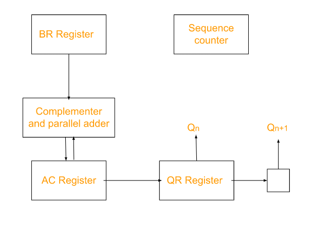
The equipment execution of the booth algorithm requires the register arrangement displayed in the figure beneath.
Booth Multiplication Algorithm in Computer Architecture Flowchart
We individually name the register A, B, Q, AC, BR, and QR. Qn assigns the most un-huge piece of the multiplier in the register QR.
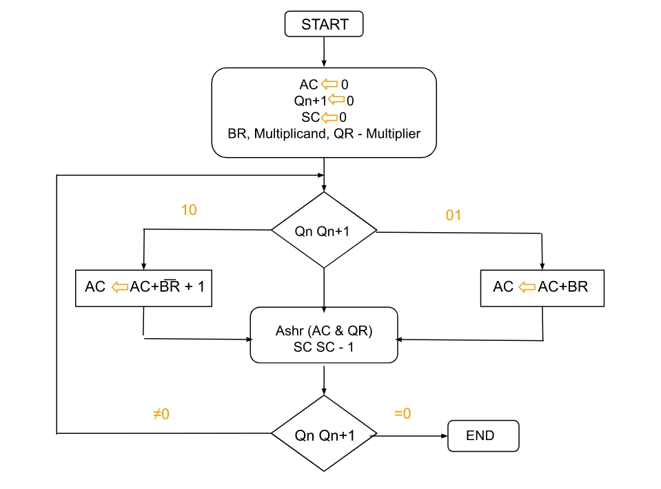
An additional flip-flop Qn+1is affixed to QR to work with a twofold multiplier review. The flowchart for the booth multiplication algorithm in computer architecture is displayed underneath.
AC and the affixed piece Qn+1 are at first cleared to 0, and the succession SC is set to a number n equivalent to the number of pieces in the multiplier.
The two parts of the multiplier in Qn and Qn+1are reviewed.
On the off chance that the two components are equivalent to 10, it implies that the initial 1 in a string has been experienced. This requires the deduction of the multiplicand from the halfway item in AC.
On the off chance that the 2 pieces are equivalent to 01, it implies that the initial 0 in a line of 0's has been experienced. This requires the expansion of the multiplicand to the halfway item in AC.
At the point when the two pieces are equivalent, the halfway thing doesn't change.
A flood can't happen because the expansion and deduction of the multiplicand follow one another. As an outcome, the two numbers added consistently have contrary signs, a condition rejecting a flood. The subsequent stage is to move right the incomplete item and the multiplier (counting Qn+1). This is a math shift right (ashr) activity in which AC and QR are to the right and leaves the signature piece in AC unaltered. The grouping counter is decremented, and the computational circle is rehashed n times. The result of negative numbers is significant; while increasing negative numbers, we want to find 2's supplement of the number to change its sign since it's more straightforward to add than performing parallel deduction. The result of two negative numbers is shown beneath alongside 2's supplement.
Example of Booth's Algorithm in Computer Architecture
Track down the result of 3 x (- 4), where m = 3, r = - 4, x = 4 and y = - 4.
A = 001100001
S = 110100000
P = 000011000
The loop must be performed multiple times since y = 4.
P = 000011000
Here, the last two pieces are 00.
In this manner, P = 000001100 in the wake of playing out the number-crunching right shift. 💡
P = 000001100
Here, the last two pieces are 00.
In this manner, P = 000000110 in the wake of playing out the number-crunching right shift.
P = 000000110
Here, the last two pieces are 10.
Consequently, P = P + S, which is 110100110.
P = 111010011 in the wake of playing out the right math shift.
P = 111010011
Here, the last two pieces are 11.
Consequently, P = 111101001, after playing out the number juggling right shift.
The item is 11110100; after dropping the LSB from P.
Set the Multiplicand and Multiplier parallel pieces as M and Q, separately.
First, we set the AC and Qn + 1 register's worth to 0.
SC addresses the number of Multiplier bits (Q), and it is a grouping counter that is persistently decremented till equivalent to the number of pieces (n) or comes to 0.
A Qn addresses the last piece of the Q, and the Qn+1 shows the increased amount of Qn by 1.
On each pattern of the booth algorithm, Qn and Qn + 1 pieces will be kept an eye on the accompanying boundaries as follows:
At the point when two pieces Qn and Qn + 1 are 00 or 11, we play out the math shift right activity (ashr) to the halfway item AC. Also, the Qn and Qn + 1 pieces are increased by 1 bit.
If the Qn and Qn + 1 pieces show to 01, the multiplicand bits (M) will be added to the AC (Accumulator register). From that point onward, we play out the suitable shift activity to the AC and QR bits by 1.
If the Qn and Qn + 1 pieces are shown to 10, the multiplicand bits (M) will be deducted from the AC (Accumulator register). From that point forward, we play out the suitable shift activity to the AC and QR bits by 1.
6. The activity worked until we arrived at n - 1 digit in the Booth Multiplication Algorithm in Computer Architecture
7. The consequences of the Multiplication of twofold pieces will be put away in the AC and QR registers.
Advantages of Booth Algorithm
Reduced Number of Partial Products: Booth multiplication reduces the number of partial products generated during multiplication, leading to fewer additions and subtractions. This results in faster multiplication operations and improved overall efficiency.
Optimized Hardware Utilization: By minimizing the number of arithmetic operations required, the Booth algorithm helps optimize hardware resources in processors. This is particularly beneficial in microprocessor designs where efficient utilization of resources is essential for performance.
Simplicity in Implementation: Despite its efficiency, the Booth algorithm is relatively simple to implement in hardware, making it suitable for various computer architectures. Its straightforward nature allows for easy integration into processor designs without significant complexity.
Disadvantages of Booth Algorithm
Increased Hardware Complexity: While the Booth algorithm simplifies the multiplication process from a computational standpoint, it may increase hardware complexity due to the need for additional circuitry to perform the Booth encoding and decoding operations. This can impact the overall chip area and power consumption.
Limited Performance Improvement for Small Multipliers: The benefits of the Booth algorithm are most pronounced for larger multiplier values. For small multiplier values, the overhead introduced by Booth encoding and decoding may outweigh the performance gains, resulting in marginal improvements.
Potential for Increased Latency: In certain scenarios, such as when handling operands with alternating patterns, the Booth algorithm may introduce additional latency compared to other multiplication methods. This latency can impact the overall throughput of the processor in certain applications.
Application of Booth’s Algorithm
Digital Signal Processing (DSP): Booth multiplication is commonly used in DSP applications where efficient multiplication of large binary numbers is essential, such as in filtering, convolution, and Fourier transform operations. Its ability to accelerate multiplication tasks makes it well-suited for real-time signal processing.
High-Performance Computing (HPC): In high-performance computing environments, Booth multiplication can be employed to enhance the computational efficiency of processors, particularly in scientific simulations, numerical analysis, and matrix operations where extensive multiplication operations are involved.
Embedded Systems: Booth multiplication finds applications in embedded systems and microcontroller designs where resource-efficient algorithms are crucial for achieving optimal performance within constrained hardware environments. Its balance of efficiency and simplicity makes it a suitable choice for various embedded computing tasks, including image processing, communication protocols, and control systems.
Frequently Asked Questions
What is implied by Booth's calculation?
Booth duplication calculation is an augmentation calculation that duplicates two marked parallel numbers in two's supplement documentation.
What is the utilization of the Booth multiplier?
Booth multiplier is the math administrator for DSP applications, for example, sifting and for Fourier changes. Stall multiplier is utilized to accomplish high execution speed. These multipliers will generally consume a large portion of force in DSP calculation.
What are the elements of Booth calculation?
Elements of stall calculation are Serial Communication, I/O, Channels, Interleaved Memory, RISC/CISC Processors and so forth
What is the benefit of Booth calculation?
Stall calculation gives the technique of increase of double numbers with 2's supplement portrayal, subsequently uses of augmentations and deductions would be diminished.
Which shift is utilized in augmentation calculation?
The left shift of the multiplicand moves the halfway items to one side, similarly as while increasing by paper and pencil.
What is the 16 bit Booth Algorithm?
The 16-bit Booth Algorithm is an efficient method for binary multiplication using Booth's encoding, reducing the number of arithmetic operations by handling positive and negative multipliers optimally, improving performance for signed binary numbers.
Conclusion
We have read that Booth Multiplication Algorithm in Computer Architecture calculation is an increase calculation that increases two substantial parallel numbers in two's supplement documentation. Speeding up the introduction of the expanded interaction is moreover utilized. It is also particularly compelling. Booth Multiplication manages the string pieces 0's in the multiplier, requiring no additional work this can be done by Simply shifting the right-most string pieces and a line of 1's in a multiplier bit. Further, we have completed a detailed discussion on the hardware implementation of the algorithm with examples.


 8+ registered

