Do you think IIT Guwahati certified course can help you in your career?
Introduction
A class diagram is a type of UML (Unified Modeling Language) diagram that provides a high-level view of the structure and relationships between classes in an object-oriented software system. It is a visual representation that helps software developers and other stakeholders to understand the system's design and architecture.
Class diagrams are widely used in system design and play an essential role in ensuring that the software system meets the needs and requirements of stakeholders.
This article will provide an overview of class diagrams, their importance in system design, and how to create them using UML notation.
What are Class Diagrams?
Class diagrams are one of the most commonly used types of diagrams in Unified Modeling Language (UML). They represent the static structure of a system by showing the system's classes, their attributes, methods, and the relationships between the objects. Class diagrams provide a high-level view of an application, which is essential for both understanding and designing complex systems. They are often used in object-oriented programming to visualize the design and architecture of a system before it's implemented.
What is a Class?
A class is a blueprint or template for creating objects in object-oriented programming. It defines a set of properties (attributes) and behaviors (methods) that the objects created from the class can have. A class encapsulates data for the object and the methods to manipulate that data. For example, a Car class may have attributes like color, model, and speed, and methods like accelerate(), brake(), and turn(). When a class is instantiated, it creates an object that can interact with other objects in the system.
UML Class Notation
In UML, a class is represented as a rectangle divided into three sections. The top section contains the class name, the middle section lists the attributes, and the bottom section contains the methods. Each attribute and method can have visibility markers such as + (public), - (private), and # (protected) to indicate their access levels. Additionally, the data types of the attributes and return types of the methods are often specified. UML class notation is a powerful tool for visualizing and communicating the structure and design of a system in a standardized way.
Relationships Between Classes
In UML class diagrams, relationships between classes are used to illustrate how classes interact with each other. There are several types of relationships:
Association: Represents a general relationship between two classes where objects of one class interact with objects of another.
Aggregation: A special type of association that represents a "whole-part" relationship where one class is composed of one or more classes, but the parts can exist independently.
Composition: A stronger form of aggregation where the "whole" is responsible for the lifecycle of the parts, meaning if the whole is destroyed, the parts are destroyed as well.
Inheritance (Generalization): Represents an "is-a" relationship where one class (child) inherits the properties and methods of another class (parent).
Dependency: Indicates that a change in one class may affect another class, but the relationship is typically temporary and weak.
These relationships help to define how classes in a system are connected and interact, which is crucial for understanding the system's behavior and structure.
Where are Class Diagrams Used?
Class diagrams are used in the early stages of system design to provide a high-level view of the system's structure. They are particularly useful for software developers, project managers, and other stakeholders involved in designing and developing object-oriented software systems. Class diagrams help stakeholders understand the relationships between classes, their attributes, and the methods they can use to interact with each other.
In addition to software development, class diagrams are used in other industries such as engineering, healthcare, and finance. They can be used to model complex systems and their relationships, helping to ensure that the system being designed meets the needs and requirements of stakeholders.
Purpose of Class Diagrams
Class diagrams serve as a blueprint for the design and development of object-oriented systems. Their primary purpose is to visually represent the static structure of a system, detailing the various classes and the relationships among them. This allows developers and stakeholders to understand the system's architecture and make informed decisions during the design phase. Class diagrams help identify a system's necessary components, define their interactions, and ensure that the system's structure is logical and scalable. They are also crucial in the documentation process, providing a clear and organized view of the system that can be referenced throughout the development lifecycle.
Benefits of Class Diagrams
Class diagrams offer several key benefits in software development:
Visualization of System Structure: They provide a clear and organized view of the system's architecture, making it easier to understand and communicate the design to stakeholders.
Facilitation of Object-Oriented Design: By illustrating classes and their relationships, class diagrams aid in designing systems that follow object-oriented principles, ensuring modularity and reusability.
Documentation: Class diagrams serve as valuable documentation, helping developers, testers, and maintainers understand the system's structure and design decisions.
Identification of Relationships: They help identify and define relationships between classes, such as inheritance, association, and dependency, which are crucial for a well-structured system.
Design Validation: Class diagrams allow for early validation of the system design, helping to identify potential issues or inefficiencies before implementation.
Support for Code Generation: Many modern development tools can generate code from class diagrams, speeding up the development process and ensuring consistency between the design and implementation.
Basic Components of a Class Diagram
Classes: Represented by rectangles, classes define the blueprint for objects with attributes and methods.
Attributes: Properties or variables of a class, specifying the data it holds.
Methods: Functions or operations that define the behavior of a class.
Associations: Relationships between classes, shown as lines connecting them. Can be one-to-one, one-to-many, or many-to-many.
Multiplicity: Indicates how many instances of a class can be related to another class.
Inheritance: Shown with a solid line and a triangle, representing a child class inheriting attributes and methods from a parent class.
Aggregation: A special type of association representing a "whole-part" relationship, where the part can exist independently of the whole.
Composition: A stronger form of aggregation where the part cannot exist without the whole.
Visibility: Specifies the accessibility of attributes or methods (public, private, or protected).
Constraints: Notes or conditions that apply to specific parts of the class diagram.
How to Create a Class Diagram?
Creating a class diagram involves a few steps, including identifying the classes, their attributes, and their relationships. Here is a simple guide to creating a class diagram:
Identify the Classes: Identify the classes in the system you want to model. Classes represent objects or entities with common characteristics, such as attributes and behaviors.
Identify the Attributes: Next, identify the attributes of each class. Attributes represent the characteristics or properties of the class, such as its name, ID, and other relevant data.
Identify the Relationships: After identifying the classes and attributes, you should identify the relationships between the classes. Relationships can be represented as associations, generalizations, or aggregations.
Draw the Diagram: Once you have identified the classes, attributes, and relationships, you can draw the class diagram using UML notation.
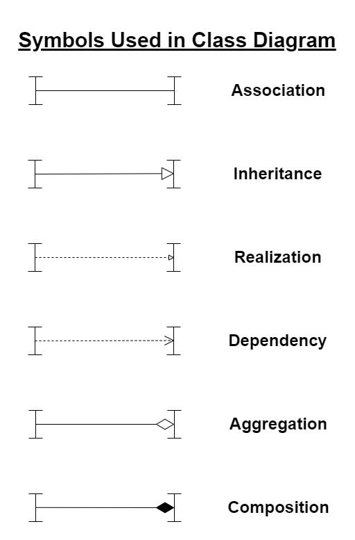
Symbols used in Class Diagram
Class diagrams in UML use a set of standardized symbols to represent various elements and relationships within a system. Here are some of the standard symbols used in class diagrams:
Class symbol: A rectangular box with the name of the class inside it, usually at the top. It may also include the class's attributes and methods.
Attribute symbol: A small box attached to the class symbol that lists the class's attributes.
Method symbol: A small box attached to the class symbol lists the class methods.
Visibility indicator: A small symbol next to the attribute or method that indicates its visibility, such as a plus sign (+) for public, a hash symbol (#) for protected, or a minus sign (-) for private.
Association line: A line connecting two classes that indicates a relationship between them.
Multiplicity indicator: A number or range placed next to the association line that indicates the number of instances of one class that can be associated with instances of the other class.
Inheritance arrow: A solid line with a closed, unfilled arrowhead that indicates that one class inherits from another.
Interface realization arrow: A dashed line with a closed, unfilled arrowhead that indicates that a class implements an interface.
Aggregation diamond: A hollow diamond shape on the end of an association line that indicates a relationship in which one class is part of another class.
Composition diamond: A filled diamond shape on the end of an association line that indicates a relationship in which one class owns or contains another class.
These symbols are used to create class diagrams that represent the structure of a system, including its classes, attributes, methods, and relationships. Using standardized symbols, class diagrams provide a clear and concise way to communicate the design of a system to stakeholders, including developers, project managers, and other development team members.
Example of Class Diagram
Here are two examples of class diagrams:
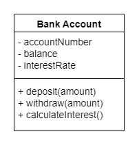
1. Bank Account Class Diagram:
In this example, we have a Bank Account class with three private attributes: accountNumber, balance, and interestRate. The class has three public methods: deposit, withdraw, and calculateInterest.
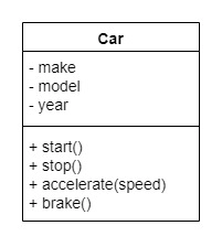
2. Car Class Diagram:
In this example, we have a Car class with three private attributes: make, model, and year. The class has four public methods: start, stop, accelerate, and brake.
Both of these examples demonstrate how a class diagram can be used to represent the attributes and methods of a class in a clear and organized way. They are useful tools for understanding the structure of a software system and communicating that structure to other developers.
The Importance of Class Diagrams in System Design
Class diagrams play an important role in system design as they provide a clear and concise representation of the system's structure. By using class diagrams, developers can identify potential design flaws or inefficiencies before the system is implemented, which can save time and resources. Class diagrams also help stakeholders to communicate and collaborate more effectively, ensuring that everyone has a clear understanding of the system's structure and relationships.
Moreover, class diagrams can be used to generate code, making it easier for developers to implement the system. Code generation tools can use class diagrams to create code templates, which can be customized and refined as needed.
Frequently Asked Questions
What are the three main elements of a class diagram?
The three main elements of a class diagram are classes, attributes, and methods, representing the structure and behavior of objects in the system.
What is a class diagram line?
A class diagram line represents relationships between classes, such as associations, inheritance, aggregation, or composition, indicating how classes interact or depend on each other.
What is the role of a class diagram?
The role of a class diagram is to visually represent the structure, relationships, and interactions between classes in an object-oriented system for system design.
Conclusion
In this article, we have discussed what a Class Diagram is. Class diagrams are fundamental tools in object-oriented design, providing a clear and structured way to visualize the static architecture of a system. By representing classes, their attributes, methods, and relationships, class diagrams enable developers and stakeholders to understand, communicate, and document the system's structure effectively.


 8+ registered

