Do you think IIT Guwahati certified course can help you in your career?
Introduction
A sequence diagram is a type of interaction diagram that shows the interactions between objects or components of a system in chronological order. It shows the sequence of messages exchanged between different components or objects in the system to accomplish a specific task or scenario.
Sequence diagrams are often used in software engineering and systems design to visualize the dynamic behavior of a system, including how various components interact with each other and the order in which actions occur. They can be used to identify potential issues, clarify complex processes, and communicate design ideas to stakeholders.
Learn all about Sequence Diagrams - a popular tool used in system design - in this comprehensive guide. Discover where Sequence Diagrams are used, the symbols used to create them, and how to create them yourself.
Where are Sequence Diagrams used?
Sequence diagrams are used in software development and system design to visualize and understand the flow of interactions between different components or objects in a system. They are particularly useful in modeling complex systems with many components and interactions, as they provide a clear and concise representation of the sequence of events that occur during the execution of a system.
Sequence diagrams are commonly used to develop web applications, mobile applications, and other software systems.
Symbols used in Sequence Diagram
UML Sequence Diagrams display a timeline with symbols and notations to standardize the structure. The diagram flows from top to bottom to represent the sequence of interactions and objects in the system.
The followings are the symbols and notations commonly used in UML Sequence Diagrams:
1.Lifeline: Used to represent each instance in the interaction.
2. Actor: Used to specify a role played by a user or system that interacts with the system's objects.
3. Activity: Denotes a major task required to fulfill an operation contract.
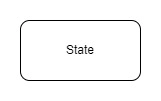
4. State: Denotes the condition of an event or activity in the system and states changes triggered by events.
5. Object Flow: This shows the path through which data passes.
6. Bars: Indicate the diagram's start or end of concurrent activities.
7. Initial State: Denotes the initial state of the workflow, shown by a circle.
8. Control Flow: This shows the order in which program instructions are executed, represented by an arrow.
9. Decision Activity: Indicates where a decision is taken, represented by a diamond shape.
10. Objects: Represents an instance of a class in a rectangular shape.
11. Package: Used to contain interactive elements, shown in a rectangular shape with an inner rectangle to label the diagram.
Common Message Symbols are also used in UML Sequence Diagrams to show how information is transmitted between different objects in the Structure Diagram. These symbols include
1.Synchronous Message: Denotes when the sender must wait for a response to a message before continuing, shown by a symbol.
2. Asynchronous Message: This does not require a reply from the receiver before continuing, represented by a lined arrowhead.
3. Create Message: Used when creating a new object in the sequence diagram, represented by "created" on top of a dotted arrow.
4. Delete Message: Represents the deletion of an object, indicated by an "X" at the end of an arrow.
5. Self Message: Used when an object needs to send a message to itself, shown with a U-shaped arrow.
How to create a sequence diagram?
Here are the general steps for creating a sequence diagram:
Identify the Actors: The first step in creating a sequence diagram is identifying the actors or components involved in the system or process you are modeling. Actors can be individuals, systems, or external entities interacting with the system.
Identify use cases: Identify the specific tasks or use cases the system needs to perform. This will help you identify the interactions between actors and components.
Determine the sequence of events: Determine the sequence of events or messages that must be exchanged between actors and components. This can be done by analyzing the use cases and identifying the dependencies between the various elements.
Create Objects: Create objects or components that will be involved in a sequence of events. Each item should be represented by a lifeline, which is a vertical line that represents the item over time.
Add messages: Add messages between objects to represent interactions that occur during a sequence of events. These messages can be synchronous (indicated by a solid arrow) or asynchronous (indicated by a dashed arrow) and may include parameters and return values.
Add time constraints: Add time constraints to the diagram to indicate the duration of each message or operation. This can be done using activation bars and shaded areas representing the duration of an operation or message.
Refine the diagram: Refine the sequence diagram as needed, adding more details or adjusting the sequence of events to represent the process being modeled accurately.
Overall, creating a sequence diagram requires careful analysis of a system or process model and an understanding of the interactions between the various actors and components involved. With careful planning and attention to detail, a well-designed sequence diagram can be invaluable in system design and development.
Example of Sequence Diagram
This sequence diagram visually represents the flow of activities involved in an online shopping process.
The above sequence diagram depicts the interaction between different systems involved in an online shopping process. It starts with the user browsing through the products on the website and adding items to their cart. The website then communicates with the inventory system to get the product list and adds the selected items to the shopping cart. Finally, the user proceeds to checkout, and the website processes the payment via a payment gateway and sends the order details to the order fulfillment system for delivery.
Sequence diagrams are important in system design for the following reasons:
Visualizing system behavior: Sequence diagrams provide a visual representation of how objects in a system interact with each other and the order in which these interactions occur. It helps in understanding the behavior of the system as a whole.
Identifying design flaws: Sequence diagrams help identify potential design flaws and issues early in the design process. This can save time and money by preventing the need for costly redesigns later.
Communication: Sequence diagrams can be used as a communication tool between the various stakeholders involved in the design process, including developers, architects, and business analysts. They provide a common language that can be easily understood by everyone involved.
Testing: Sequence diagrams can be used as the basis for testing a system. By understanding the sequence of object interactions, testers can develop test cases that cover all possible scenarios.
Overall, sequence diagrams are an important tool in system design that can help ensure that the final product is efficient, effective, and meets the needs of all stakeholders involved.
Frequently Asked Questions
How does UML help in modeling complex systems?
UML provides a standardized way to represent and visualize complex systems, making it easier to understand and communicate the system's design and structure.
How can UML be integrated with other software development tools?
UML models can be integrated with other software development tools, such as version control systems, project management tools, and code generation tools.
What are some best practices for using UML in software design and development?
Some best practices for using UML include keeping diagrams simple and clear, using consistent notation and terminology, and regularly reviewing and updating the UML models as the software evolves.
Conclusion
A sequence diagram is a type of diagram that shows the interactions between components or objects in a system in chronological order. It is often used in software engineering to visualize the dynamic behavior of a system and how different components interact with each other to accomplish a specific task.
Sequence diagrams are particularly useful for modeling complex systems with many interactions, as they provide a clear and concise representation of the sequence of events that occur during the execution of a system. They are commonly used to develop web applications, mobile applications, and other software systems.
Symbols used in sequence diagrams include actors, lifelines, objects, messages, activations, self-messages, return messages and barriers. To create a sequence diagram, you need to identify the actors, use cases, and sequence of events. Then, you create objects, add messages and add time constraints to the diagram.
Sequence diagrams are important in system design for visualizing system behavior, identifying design flaws, communicating design ideas to stakeholders, and testing the system. With careful planning and attention to detail, a well-designed sequence diagram can be invaluable in system design and development.
We encourage you to enhance your expertise and skills in system design by utilizing our guided path, which provides a thorough understanding of all the fundamental concepts necessary to embark on your system design journey.
We trust that you have found this blog informative and valuable. Please feel free to share your feedback and insights in the comments section.


 8+ registered

