Do you think IIT Guwahati certified course can help you in your career?
What is Unified Modeling Language?
UML stands for Unified Modeling Language. It is a standardized visual modeling language used to describe and design software systems, particularly object-oriented ones. UML provides a set of notations and diagrams that are used to represent different aspects of a system, such as its structure, behavior, and interactions with external entities.
UML was created by the Object Management Group (OMG), a consortium of software vendors and industry experts, in the 1990s. It has become the de facto standard for modeling software systems, and is widely used in software development and engineering.
Some of the common types of diagrams used in UML include class diagrams, use case diagrams, sequence diagrams, activity diagrams, and state diagrams. These diagrams help to visualize the structure and behavior of a software system. They can aid in communication among software developers, project managers, and other stakeholders involved in the software development process.
This article provides an overview of UML, the Unified Modeling Language, and explains why it is used in system design. It also describes the various types of UML diagrams, their purpose, and how they can be used to model complex systems. Whether you're a software developer or project manager, this article offers valuable insights into the benefits of UML and how it can improve the quality of software systems.
Why do we use UML in system design?
UML is used in system design for several reasons:
UML provides a common visual language for communicating design ideas and requirements among different stakeholders, helping to avoid misunderstandings and ensuring everyone involved in the project clearly understands the system's purpose and function.
Additionally, UML provides a range of specialized notations and diagrams that are tailored to represent various aspects of software systems, including their structure, behavior, and interactions with external entities. This helps ensure that the design is thorough and covers all of the critical elements of the system.
Moreover, UML offers a flexible and adaptable methodology for system design, allowing for the modeling of systems at various levels of abstraction, from high-level overviews to detailed designs. It can be applied to various types of systems, including object-oriented, component-based, and distributed systems.
Lastly, UML can enhance the quality of software systems by facilitating the early detection of potential problems or design flaws. By visualizing the system design in advance, developers can identify potential issues and modify the design before implementing the system, resulting in better-quality software.
Where are UML diagrams used in system design?
UML has a wide range of applications in system design, especially in software development. It ensures that the system being developed meets the requirements and specifications of stakeholders, and that the design is well-structured. UML can be used to model various types of software systems, such as object-oriented, component-based, and distributed systems.
Apart from software systems, UML is also utilized in non-software systems design, such as business processes, organizational structures, and complex systems. UML can help identify inefficiencies, redundancies, and areas for improvement in a system.
Moreover, UML is extensively used in various industries, such as healthcare, finance, transportation, and aerospace, to model complex systems like medical devices, financial systems, and transportation networks. This ensures that these systems are safe, efficient, and effective.
Overall, UML is a powerful and flexible tool that can be used in many different contexts to design and model complex systems. It benefits software developers, project managers, and other stakeholders involved in system design.
Types of UML Diagrams
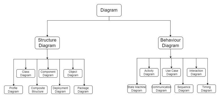
UML diagrams are divided into two groups. The two groups are structural diagrams and behavioral diagrams.
Structural Diagrams: Structural diagrams represent the static elements of a system, such as classes, objects, interfaces, components, and physical components. The structural diagrams include the following:
Class diagram: Shows the classes and their relationships in a system and the attributes and methods of each class.
Object diagram: Shows the objects and their relationships in a system at a specific point in time.
Component diagram: Shows the components and their relationships in a system and the interfaces provided by each component.
Deployment diagram: Shows a system's physical hardware and software components and how they are deployed across different nodes.
Package diagram: Shows the packages and their dependencies in a system and the organization of the system's modules.
2. Behavioral Diagrams: Behavioral diagrams represent the dynamic aspects of a system, such as the interactions between objects, the changes in the system state, and the flow of control within the system. The behavioral diagrams include the following:
Use case diagram: Shows the interactions between actors and the system and the different use cases the system supports.
Sequence diagram: Shows the interactions between actors and the system and the different use cases the system supports.
Collaboration diagram: Similar to a sequence diagram, but shows the interactions between objects in a system from a different perspective.
Statechart diagram: Shows the different states of an object in a system and the events that trigger transitions between those states.
Activity diagram: Shows the flow of activities in a system and the actions and decision points involved in each activity.
Timing diagram: Shows the timing constraints of a system and the duration of different events and actions.
Interaction overview diagram: Shows an overview of the interactions between objects in a system and how they are organized into different sequences and alternatives.
Communication diagram: This shows the interactions between objects in a system and the messages exchanged between them, similar to a collaboration diagram.
Each diagram type serves a specific purpose in modeling a system or software application. They can be combined to provide a comprehensive view of the system's structure and behavior.
Frequently Asked Questions
Who uses UML diagrams?
UML diagrams are commonly used by software developers, system architects, project managers, and other stakeholders involved in the design and development of software systems.
What are the benefits of using UML?
Some of the benefits of using UML include improved communication and collaboration among stakeholders, better understanding of system requirements, easier design documentation, and more efficient development.
What are the limitations of UML?
One limitation of UML is that creating and maintaining diagrams for large and complex systems can be complex and time-consuming. Additionally, UML may not be suitable for modeling non-object-oriented systems or systems with non-linear behavior.
Conclusion
In simple terms, UML (Unified Modeling Language) is a standardized visual language used to design and describe software systems. It provides a set of diagrams and notations that help to represent different parts of the system, such as its structure, behavior, and how it interacts with external elements.
UML is widely used in system design, particularly in software development, because it helps to ensure that the system meets the requirements and specifications of the stakeholders. UML can be used to model various types of software systems, such as object-oriented, component-based, and distributed systems.
Apart from software systems, UML is also used in other fields like business processes, organizational structures, and complex systems to identify areas for improvement and increase efficiency.
There are two groups of UML diagrams: structural and behavioral diagrams. Structural diagrams represent the static elements of the system, like classes and objects, while behavioral diagrams represent the dynamic aspects of the system, such as its interactions between objects and the flow of control within the system.
Understanding the different types of UML diagrams and how they are used is essential for effective communication and collaboration among stakeholders in the system design process, which can ultimately lead to better-quality software and more efficient systems.
You can also consider our System Design Course to give your career an edge over others.
We value your feedback and thoughts, so don't hesitate to share them with us in the comments section. Together, let's delve deeper into the world of system design.
Live masterclass
Zero to Data Analyst: Amazon Analyst Roadmap for 30L+ CTC
by Abhishek Soni
17 Jun, 2026
12:30 PM
Python + AI Skills to Ace 30 LPA+ Data Roles
by Prerita Agarwal
15 Jun, 2026
12:30 PM
Build Your GenAI Interview Copilot to ace 30L+ Roles at Google
by Saurav Prateek
16 Jun, 2026
12:30 PM
Top 5 GenAI Projects to Crack 25 LPA+ Roles in 2026
by Shantanu Shubham
18 Jun, 2026
12:30 PM
Zero to Data Analyst: Amazon Analyst Roadmap for 30L+ CTC


 7+ registered