Do you think IIT Guwahati certified course can help you in your career?
Introduction
Use case diagrams are essential for visualizing how a software system functions. They define different use cases—tasks users perform—ensuring the software meets stakeholder needs. For example, in an e-commerce website, a use case diagram illustrates actions like browsing products, adding to the cart, and checking out. Understanding use case diagram notations and steps to create them helps developers build user-friendly systems.
Creating a use case diagram ensures all essential functionalities users need are considered. Use case diagrams to help communicate system functionality to stakeholders, including project managers who may not have technical expertise. With a visual representation, understanding and discussing system requirements becomes easier. This article explores the importance of use case diagrams, their notations, and how to create them in software development.
Steps for Creating a Use Case Diagram
Creating a use case diagram involves several steps:
Identify Actors: The first step is identifying the different actors interacting with the system. Actors are the users, devices, or external systems using the software. Examples of actors include customers, employees, and suppliers.
Identify Use Cases: Once you have identified the actors, the next step is identifying the different use cases or functions the software system must perform for each actor. Use cases describe specific actions an actor can take with the software system.
Create Use Case Diagram: You can create a use case diagram after identifying the actors and use cases. The diagram consists of use cases, actors, and lines showing their relationship. Actors are represented as stick figures, and use cases are represented as ovals. The lines between them show the association between actors and use cases.
Refine the Diagram: Once you have created the initial diagram, refine it by adding additional use cases, actors, and relationships. You can also group related use cases into subsystems to make the diagram more manageable.
Validate the Diagram: Finally, validate the use case diagram to ensure it accurately represents the system's requirements. Review the diagram with stakeholders to ensure all necessary functionality is included, and the diagram is easy to understand.
Creating a use case diagram is an important step in the software development process. By identifying the actors, use cases, and relationships between them, you can ensure that the software system meets user and stakeholder requirements.
Notations Used in Use Case Diagrams
Use case diagrams to use specific notations to represent actors, use cases, and relationships between them. The main notations used in use case diagrams are:
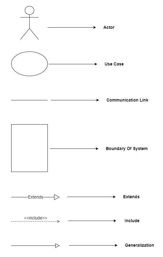
1.Actors: Actors are represented by stick figures. An actor is someone or something that interacts with the system, such as a user or an external system. Actors are drawn outside of the use case diagram and connected to the use cases they interact with.
2. Use Cases: Use cases are represented by ovals. Each use case represents a specific functionality that the system must perform. Use cases are labeled with a descriptive name and can be grouped into subsystems.
3. Relationships: Relationships are represented by lines between actors and use cases. There are three types of relationships in use case diagrams:
Association: An association shows that an actor interacts with a specific use case. It is represented by a solid line.
Generalization: A generalization shows that one use case is a more specific version of another use case. It is represented by a solid line with a triangle pointing to the more general use case.
Include: An include shows that one use case includes another use case as a step in its process. It is represented by a dotted line with an arrow pointing to the included use case.
4. System Boundary: The system boundary is represented by a rectangle that contains the use cases and actors. It shows the boundaries of the system being modeled.
These notations provide a clear and standardized way to represent the functional requirements of a software system in a use case diagram. By using these notations, developers, stakeholders can easily understand how the system works and how different actors interact with it.
Examples of Use Case Diagram
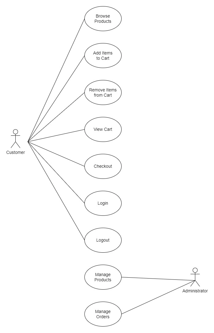
Online Shopping System
In this example, the use case diagram shows the different actors and use cases involved in an online shopping system.
Actors:
Customer
Administrator
Use Cases:
Browse products
Add item to cart
Remove item from cart
View cart
Checkout
Login
Logout
Manage products
Manage orders
Relationships:
The customer can browse products, add items to the cart, remove items from the cart, view the cart, checkout, log in, and log out.
The administrator can manage products and manage orders.
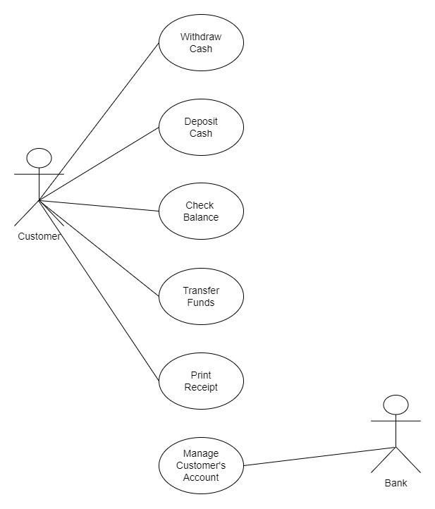
ATM System
In this example, the use case diagram shows the different actors and use cases involved in an ATM system.
Actors:
Customer
Bank
Use Cases:
Withdraw cash
Deposit cash
Check balance
Transfer funds
Print receipt
Manage Customer’s Accounts
Relationships:
The customer can withdraw cash, deposit cash, check balance, transfer funds, and print receipts.
The bank provides the system and manages the customer's accounts.
Importance of Use Case Diagram
Use case diagrams are an important aspect of software development because they provide several benefits, including:
Requirements Gathering: Use case diagrams help capture the functional requirements of a software system by defining the different use cases and actors that interact with the system. This makes it easier to understand and prioritize the features that the system must have.
Communication: Use case diagrams clearly represent how the software system works and how users interact with it. This makes communicating the system's functionality easier to stakeholders, including project managers, developers, and users.
Testing: Use case diagrams can also be used to design and execute test cases, which help ensure that the system works as intended. Test cases can be designed based on the different use cases identified in the use case diagram.
Maintenance: Using case diagrams also makes it easier to maintain the software system by clearly understanding how the system works. This allows developers to identify and fix issues as they arise quickly.
Scalability: Use case diagrams can be used to identify potential areas for future expansion or enhancement of the software system. This allows the development team to plan for future growth and ensure that the system can easily adapt to meet changing user needs.
Frequently Asked Questions
What is an association relationship in UML?
An association relationship in UML represents a connection between two or more classes. It can be unidirectional or bidirectional and can have attributes and multiplicities to specify the nature of the relationship.
What is an aggregation relationship in UML?
An aggregation relationship in UML represents a "has-a" relationship between classes where one class contains a collection of objects of another class. It is an association where the whole can exist without the parts.
What is a composition relationship in UML?
A composition relationship in UML represents a "part-of" relationship between classes where one class contains a collection of objects of another class. It is an association where the whole cannot exist without the parts.
Conclusion
In conclusion, use case diagrams are an essential tool in software development, helping developers and stakeholders understand and communicate a system's functional requirements.
Developers can create a clear and accurate representation of the system's functionality by following the steps for creating a use case diagram and using the standardized notations.
Use case diagrams provide several benefits, including gathering requirements, communication, testing, maintenance, and scalability. Therefore, developers need to understand the importance of use case diagrams and use them in their software development processes.


 8+ registered

