Last Updated: 19 Dec, 2020

AVL Tree: Insert

Easy
Asked in companies
VisaMTX

Problem statement

Given an AVL tree, insert an element in the AVL Tree.

An AVL tree is a self-balancing binary search tree.

It has the following properties:

1. It has the property of the binary search tree , i.e for every node , the nodes in its left subtree is less than the node and nodes in the right subtree is greater than the current node.

2. The absolute difference between the height of left subtree and right subtree of any node is less than or equal to 1.

Read more about AVL Tree Here: https://en.wikipedia.org/wiki/AVL_tree

For example:

The numbers in white beside the nodes denote the height of the tree. We can see when we insert 7 in the tree it imbalances the tree at node 10 and hence we do a rotation to rebalance it. FInally we return the in order traversal of the final tree.

Note
1.Do not print anything, just return the root node of the tree.
2.Your constructed tree will be checked by doing an in-order traversal of the tree from the returned root node.
Input Format:
The first line contains an Integer 't' which denotes the number of test cases or queries to be run. Then the test cases follow.

The first line of input contains the elements of the tree in the level order form separated by a single space.
The second line contains an integer denoting the value to be inserted
If any node does not have left or right child, take -1 in its place. Refer to the example below.

Example:

Elements are in the level order form. The input consists of values of nodes separated by a single space in a single line. In case a node is null, we take -1 on its place.

For example, the input for the tree depicted in the below image would be :
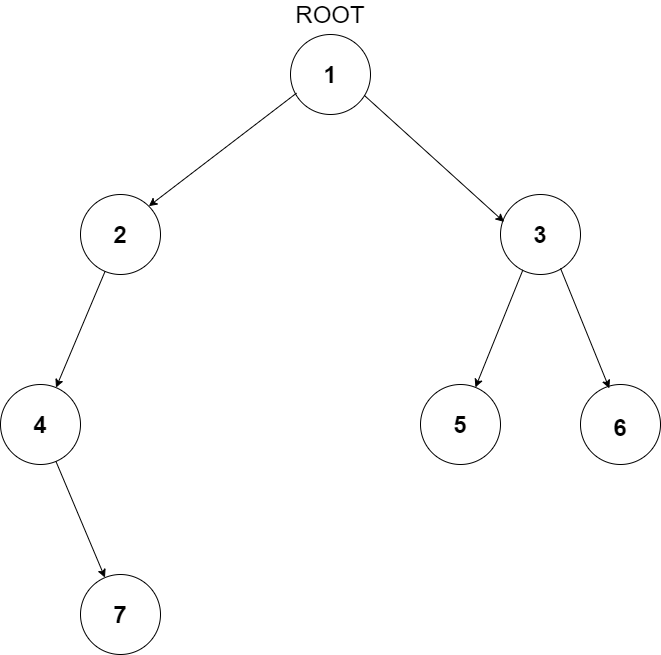
example

1
2 3
4 -1 5 6
-1 7 -1 -1 -1 -1
-1 -1

Explanation :
Level 1 :
The root node of the tree is 1

Level 2 :
Left child of 1 = 2
Right child of 1 = 3

Level 3 :
Left child of 2 = 4
Right child of 2 = null (-1)
Left child of 3 = 5
Right child of 3 = 6

Level 4 :
Left child of 4 = null (-1)
Right child of 4 = 7
Left child of 5 = null (-1)
Right child of 5 = null (-1)
Left child of 6 = null (-1)
Right child of 6 = null (-1)

Level 5 :
Left child of 7 = null (-1)
Right child of 7 = null (-1)

The first not-null node (of the previous level) is treated as the parent of the first two nodes of the current level. The second not-null node (of the previous level) is treated as the parent node for the next two nodes of the current level and so on.

The input ends when all nodes at the last level are null (-1).
Note :
1.The above format was just to provide clarity on how the input is formed for a given tree.

2.The sequence will be put together in a single line separated by a single space. Hence, for the above-depicted tree, the input will be given as:

1 2 3 4 -1 5 6 -1 7 -1 -1 -1 -1 -1 -1
Output Format
For each test case, the root node of the AVL tree with the given node inserted.
Constraints:
1 <= T <= 100
1<= N <= 3*10^3

Where ‘T’ is the total number of test cases and N denotes the number of nodes in the given binary tree.

Time limit: 1 second

Approaches

01 Approach

  • The idea is to insert the node as we do in a traditional  BST and then go up the tree to find the first point of imbalance, i.e the place where the balance factor of the node is greater than or equal to two.
  • Balance factor of a node is defined as the absolute difference between the number of nodes of the Left Subtree and the right subtree.
  • If, for all the nodes from the newly inserted node to the root node of the tree, the balance factor is 0 1 or -1 the tree is already balanced and we do not need to do anything.
  • Otherwise, 4 cases may arise which are as follows:
    • If there is an imbalance in the right child of the left subtree, then you perform a left-right rotation.


  • If there is an imbalance in the right child of right subtree, then you perform a left rotation.
  • If there is an imbalance left child of the right subtree then you perform a right-left rotation
  • If there is an imbalance in the left child of left subtree, then you perform a right rotation.

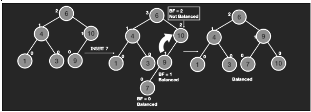
Keeping in mind the above idea, we can devise the following recursive  approach:

  • Insert the node in the tree as we do in a traditional BST and update the height of all of the ancestors of the newly inserted node.
  • While Calculating the height, Also calculate the balance factor of the ancestors, which is the difference in the height of left subtree and right subtree.
  • If the Balance Factor is greater than 1 we either need to do a left left rotation or left right rotation.
  • If it is a left left case, the newly inserted node will be in the left child of the left subtree of the current node, i.e it will be less than the left child of the current node. Otherwise, it is the left right case.
  • To do a left rotate, let us assume that we do it at a node ‘x’ then we define 2 variables, ‘rightSubTreeRoot’ which is the right node of the current node and also the root of the right subtree.Also we define another variable ‘rightSubTreeRootLeftChild’ which is the left child of the node which is the right child of the current node.
  • To perform the left rotation, we connect the left of the ‘rightSubTreeRoot’ to ‘x’ and connect the right of ‘x’ to ‘rightSubTreeRootLeftChild’
  • Then we update the heights and return the ‘rightSubTreeRoot’ as root of the rotated tree.
  • In a similar way, if the balance factor is less than -1 we need to do right left rotation or right right rotation.
  • If it is a right right case, the newly inserted node will be the in the right child of the right subtree of the current node, i.e it will be greater than the right child of the current node. Otherwise, it is the right left case.
  • To do a right rotate, let us assume that we do it at a node ‘x’ then we define 2 variables, ‘leftSubTreeRoot’ which is the left node of the current node and also the root of the left subtree.Also we define another variable ‘leftSubTreeRootRightChild’ which is the right child of the node which is the left child of the current node.
  • To perform the right  rotation, we connect the right of the ‘leftSubTreeRoot’ to ‘x’ and connect the left of ‘x’ to ‘leftSubTreeRootRightChild’
  • Then we update the heights and return the ‘leftSubTreeRoot’ as root of the rotated tree.
  • We perform the suitable rotations and update the heights of the nodes to check other nodes of the tree until we reach the root.
  • The other 2 cases are just combinations of left and right rotate.