Table of contents
1.
Introduction
2.
About Cinder
3.
Shader
3.1.
Minimal Shader
3.2.
Interpolation
3.3.
Sending Data to GLSL
3.4.
Textures in Shader
3.5.
Manipulating the Vertex shader
4.
Frequently Asked Questions
4.1.
What is the difference between C++ - based openFrameworks and Cinder?
4.2.
What is the use of Cinder?
4.3.
What is the cinder framework?
4.4.
What is OpenGL?
4.5.
What is the difference between GPU and Raster in graphics in Cinder?
5.
Conclusion
Last Updated: Mar 27, 2024
Medium

Cinder - Basic Shaders

Author Sagar Mishra
0 upvote
Career growth poll
Do you think IIT Guwahati certified course can help you in your career?

Introduction

Hey Ninjas! As you all know, designing something is a work that excites many people in today's world. We have made so many designs on paper, clothes, etc. But have you ever tried to make designs using a programing language? Isn't it exciting and challenging at the same time?

Cinder - Basic Shaders

So, moving ahead with this excitement, we are here with a design tool named Cinder. Our today's topic is Basic Shaders in Cinder. Let's cover all the basic details one by one.

About Cinder

Cinder

Cinder is an open-source and free library for skilled, quality creative coding in C++. The cinder library helps with Graphics, Geometry, Audio, Video, and Texture inclusion. It was released in the spring of 2010 as a public tool. It is generally used in a non-browser environment.

Cinder is an OpenStack Block Storage service. It virtualises the control of block storage devices. Also, it offers end users a self-service API to request and use those resources without requiring any knowledge.

Shader

The Shader is a program written in OpenGL Shading Language (GLSL) in the case of OpenGL, which runs on the GPU. This is as opposed to the C++ code, which runs on the CPU.

There are two types of Shaders:

  1. Vertex shader: The Vertex shader works on each vertex of the geometry to which we are applying it.
     
  2. Fragment shader: The fragment shader works on each pixel, which is interpolated across a triangle when the given geometry is rasterised.
     

Let's now look at some examples of Basic Shaders in Cinder.

Minimal Shader

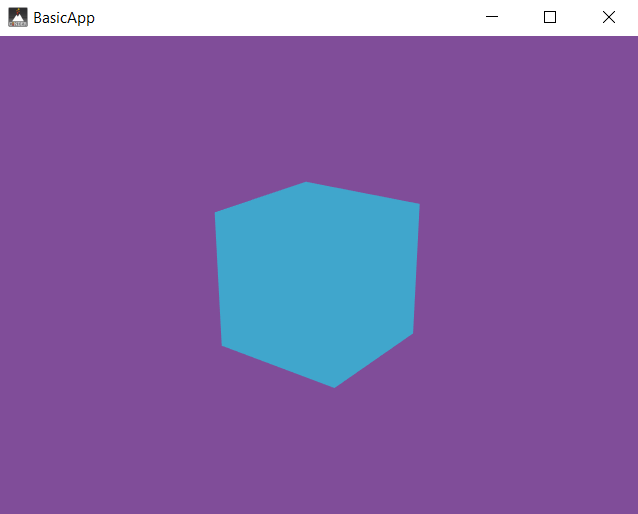
We will now see a simple example code of Minimal Shader under the Basic Shaders in Cinder. Let's start.

#include "cinder/app/App.h"
#include "cinder/app/RendererGl.h"
#include "cinder/gl/gl.h"
#include "cinder/ImageIo.h"
#include "cinder/Log.h"

using namespace ci;
using namespace ci::app;

class BasicApp : public App {
	public:
	void setup() override;
	void draw() override;

	CameraPersp         mCam;
	gl::BatchRef        mCube;
	gl::GlslProgRef mGlsl;
};

void BasicApp::setup()
{
	mCam.lookAt(vec3(3, 2, 4), vec3(0));

	mGlsl = gl::GlslProg::create(gl::GlslProg::Format()
	.vertex(CI_GLSL(150,
	uniform mat4 ciModelViewProjection;
	in vec4 ciPosition;

	void main(void) {
		gl_Position = ciModelViewProjection * ciPosition;
	}
	))
	.fragment(CI_GLSL(150,
	out vec4 oColor;

	void main(void) {
		oColor = vec4(0.0, 1.0, 2.0, 0.5);
	}
	)));

	mCube = gl::Batch::create(geom::Cube(), mGlsl);

	gl::enableDepthWrite();
	gl::enableDepthRead();
}

void BasicApp::draw()
{
	gl::clear(Color(0.5f, 0.3f, 0.6f));
	gl::setMatrices(mCam);
	mCube->draw();
}

CINDER_APP(BasicApp, RendererGl( RendererGl::Options().msaa( 16 ) ) )
You can also try this code with Online C++ Compiler
Run Code


Output:

Minimal Shader

Explanation:

In the above example, we have used the gl::GlslProg::create() method and passed it a gl::GlslProg::Format. This will construct the CI_GLSL macro for both the vertex() and fragment(). 

In the CI_GLSL, we have passed the number 15, which tells us about the targeting OpenGL version. We also used the gl::setMatrices() method to set or fix the camera position.

There are mainly two roles of the Vertex shader.

  1. The Vertex shader is responsible for defining the features we want the fragment shader to have access to.
     
  2. Vertex shaders take vertex positions shown in Object space and output them as positions in the Clip space.
     

The role of the Fragment shader is to set a final pixel colour. As you can see in the code, we encountered the out variable oColor, which records the results. 

Interpolation

We will now look at how variables can be interpolated across a polygon shape using the vertex shader.

Let's first check the code example, and then we will discuss it in the Explanation part.

#include "cinder/app/App.h"
#include "cinder/app/RendererGl.h"
#include "cinder/gl/gl.h"
#include "cinder/ImageIo.h"
#include "cinder/Log.h"

using namespace ci;
using namespace ci::app;

class BasicApp : public App {
	public:
	void setup() override;
	void draw() override;

	CameraPersp         mCam;
	gl::BatchRef        mRect;
	gl::GlslProgRef mGlsl;
};

void BasicApp::setup()
{
	mCam.lookAt(vec3(2, 1, 3), vec3(0));

	mGlsl = gl::GlslProg::create(gl::GlslProg::Format()
	.vertex(CI_GLSL(150,
	uniform mat4 ciModelViewProjection;
	in vec4 ciPosition;
	in vec4 ciColor;
	out vec4 Color;

	void main(void) {
		gl_Position = ciModelViewProjection * ciPosition;
		Color = ciColor;
	}
	))
	.fragment(CI_GLSL(150,
	in vec4 Color;
	out vec4 oColor;

	void main(void) {
		oColor = Color;
	}
	)));

	auto rect = geom::Rect().colors(
						Color(0, 0, 1),
						Color(1, 0, 0),
						Color(1, 0, 0),
						Color(0, 0, 1));
	mRect = gl::Batch::create(rect, mGlsl);

	gl::enableDepthWrite();
	gl::enableDepthRead();
}

void BasicApp::draw()
{
	gl::clear(Color(0.2f, 0.2f, 0.2f));
	gl::setMatrices(mCam);
	mRect->draw();
}

CINDER_APP(BasicApp, RendererGl(RendererGl::Options().msaa(16)))
You can also try this code with Online C++ Compiler
Run Code


Output:

Interpolation

Explanation:

This example is very similar to the last one. The key concepts that differ from the last example are:

  • We have used a blue-to-red gradient using the colors() method on geom::Rect. This helps us to set a different colour for each corner.
     
  • We have used the 3D CameraPersp to view it at an angle as geom::Rect is in the XY-plane.

Sending Data to GLSL

Our next topic of discussion will be how to send data from the C++ code to a GLSL program.

Let's now see a quick example code of Sending Data under the Basic Shaders in Cinder.

class BasicApp : public App {
  	public:
	void setup() override;
	void draw() override;

	CameraPersp mCam;
	gl::BatchRef mRect;
	gl::GlslProgRef mGlsl;
};

void BasicApp::setup()
{
	mCam.lookAt( vec3( 3, 2, 3 ), vec3( 0 ) );

	mGlsl = gl::GlslProg::create( gl::GlslProg::Format()
	.vertex( CI_GLSL( 150,
	uniform mat4 ciModelViewProjection;
	in vec4 ciPosition;

	void main( void ) {
	gl_Position = ciModelViewProjection * ciPosition;
	}
	) )
	.fragment( CI_GLSL( 150,
	uniform vec4 uColor;
	out vec4 oColor;

	void main( void ) {
	oColor = uColor;
	}
	) ) );

	mRect = gl::Batch::create( geom::Plane(), mGlsl );

	gl::enableDepthWrite();
	gl::enableDepthRead();
}

void BasicApp::draw()
{
	gl::clear( Color( 0.2f, 0.2f, 0.2f ) );
	gl::setMatrices( mCam );

	const int NUM_PLANES = 30;
	for( int p = 0; p < NUM_PLANES; ++p ) 
	{
		float hue = p / (float)NUM_PLANES;
		ColorAf color( CM_HSV, hue, 1, 1, 1 );
		mGlsl->uniform( "uColor", color );

		gl::ScopedModelMatrix scpMtx;
		float angle = M_PI * p / (float)NUM_PLANES;
		gl::rotate( angleAxis( angle, vec3( 1, 0, 0 ) ) );
		mRect->draw();
	}
}
You can also try this code with Online C++ Compiler
Run Code


Output:

Sending Data to GLSL

Explanation:

The above example will create a batch with the custom shader and a geom::Plane. The code will render 30 copies of the given plane, which are rotating around the Z axis and changing with a different colour. Here, we have created a new uniform uColor that is declared and used in the fragment shader.

Textures in Shader

The code to use the textures from shaders under the Basic Shaders in Cinder is given below.

#include "cinder/app/App.h"
#include "cinder/app/RendererGl.h"
#include "cinder/gl/gl.h"

using namespace ci;
using namespace ci::app;

class BasicApp : public App {
	public:
	void setup() override;
	void draw() override;

	CameraPersp mCam;
	gl::BatchRef mRect;
	gl::TextureRef mTexture;
	gl::GlslProgRef mGlsl;
	gl::Texture2dRef mTex;
};

void BasicApp::setup()
{
	mCam.lookAt(vec3(3, 2, 3), vec3(0));

	auto img = loadImage(loadAsset("texture.jfif"));
	mTex = gl::Texture2d::create(img);
	mTex->bind(0);

	mGlsl = gl::GlslProg::create(gl::GlslProg::Format()
	.vertex(CI_GLSL(150,
	uniform mat4 ciModelViewProjection;
	in vec4 ciPosition;
	in vec2 ciTexCoord0;
	out vec2 TexCoord0;

	void main(void) 
	{
		gl_Position = ciModelViewProjection * ciPosition;
		TexCoord0 = ciTexCoord0;
	}
	))
	.fragment(CI_GLSL(150,
	uniform vec4 uColor;
	uniform sampler2D uTex0;

	in vec2 TexCoord0;
	out vec4 oColor;

	void main(void) {
		oColor = texture(uTex0, TexCoord0) * uColor;
	}
	)));

	mRect = gl::Batch::create(geom::Plane(), mGlsl);

	gl::enableDepthWrite();
	gl::enableDepthRead();
}

void BasicApp::draw()
{
	gl::clear(Color(0.2f, 0.2f, 0.2f));
	gl::setMatrices(mCam);

	const int NUM_PLANES = 7;
	for (int p = 0; p < NUM_PLANES; ++p) 
	{
		float hue = p / (float)NUM_PLANES;
		ColorAf color(CM_HSV, hue, 1, 1, 1);
		mGlsl->uniform("uTex0", 0);
		mGlsl->uniform("uColor", color);

		gl::ScopedModelMatrix scpMtx;
		float angle = M_PI * p / (float)NUM_PLANES;
		gl::rotate(angleAxis(angle, vec3(1, 0, 0)));
		mRect->draw();
	}

	gl::setMatricesWindow(getWindowSize());
	gl::draw(mTex, Rectf(0, getWindowHeight() - 100,
	150, getWindowHeight()));
}

CINDER_APP(BasicApp, RendererGl(RendererGl::Options().msaa(16)))
You can also try this code with Online C++ Compiler
Run Code


Output:

Textures in Shader

Explanation:

We have modified the last example and added a solid colour with a texture. We have used a variable ciTexCoord0 in the Vertex shader. And the output is a matching TexCoord0. Coming to the fragment shader, we have used the uTex0 uniform of type sampler2D. We have called the bind() in the setup() on the texture and passed it 0. 

In this example, we used multiple texture units, so we need to specify all these texture units when we call mGlsl->uniform( "uTex0", 0 ) later.

Manipulating the Vertex shader

Let us now try to perform some more interesting manipulations in the vertex shader under the Basic Shaders in Cinder.

void BasicApp::setup()
{
	mCam.lookAt( vec3( 3, 2, 3 ), vec3( 0 ) );

	mGlsl = gl::GlslProg::create( gl::GlslProg::Format()
	.vertex( CI_GLSL( 150,
	uniform mat4 ciModelViewProjection;
	in vec4 ciPosition;
	in vec2 ciTexCoord0;
	out vec2 TexCoord0;

	float offset( vec2 uv )
	{
		return ( sin( uv.x * 15.0 ) +
		cos( uv.y * 7.0f + uv.x * 13.0f ) ) * 0.1f;
	}

	void main( void ) {
		vec4 pos = ciPosition;
		pos.y = offset( ciTexCoord0 );
		gl_Position = ciModelViewProjection * pos;
		TexCoord0 = ciTexCoord0;
	}
	) )
	.fragment( CI_GLSL( 150,
	uniform float uCheckSize;

	in vec2 TexCoord0;
	out vec4 oColor;

	vec4 checker( vec2 uv )
	{
		float v = floor( uCheckSize * uv.x ) +
		floor( uCheckSize * uv.y );
		if( mod( v, 2.0 ) < 1.0 )
		return vec4( 1, 1, 1, 1 );
		else
		return vec4( 0, 0, 0, 1 );
	}

	void main( void ) {
		oColor = checker( TexCoord0 );
	}
	) ) );

	auto plane = geom::Plane().subdivisions( ivec2( 30 ) );
	mRect = gl::Batch::create( plane, mGlsl );

	gl::enableDepthWrite();
	gl::enableDepthRead();
}

void BasicApp::draw()
{
	gl::clear( Color( 0.5f, 0.3f, 0.6f ) );
	gl::setMatrices( mCam );

	mGlsl->uniform( "uCheckSize", 30.0f );
	mRect->draw();
}
You can also try this code with Online C++ Compiler
Run Code


Output:

Manipulating the Vertex shader

Explanation:

We have used all the key features discussed earlier in this blog in this example. For example, using the CI_GLSL that tells about the version, vertex, fragments, and many more. We have used the setMatrices() method to set or fix the camera position.

Frequently Asked Questions

What is the difference between C++ - based openFrameworks and Cinder?

Cinder uses system-specific libraries for better performance, while openFrameworks affords better control over its underlying libraries.

What is the use of Cinder?

Cinder makes the library more appropriate for heavily abstracted projects, including art installations, commercial campaigns, and other advanced animation work.

What is the cinder framework?

One of the most intriguing frameworks for creative coding is Cinder. It is made in C++ for improved performance and enables rapid development of interactive applications with complex visuals.

What is OpenGL?

Open Graphics Library (OpenGL) is a cross-platform and cross-language API for rendering 2D and 3D vector graphics.

What is the difference between GPU and Raster in graphics in Cinder?

GPU is a specialised hardware responsible for handling OpenGL-related graphics. Whereas, Raster is the pixel-based graphics, slower than GPU equivalents.

Conclusion

This article discusses the topic of Basic Shaders in Cinder. In detail, we have seen the definition of a Shader, and then we have discussed the different types of shaders in detail, along with code and their explanations.

We hope this blog has helped you enhance your knowledge of Basic Shaders in Cinder. If you want to learn more, then check out our articles.

  1. Graphics in Cinder
  2. Logging in Cinder
  3. Audio in Cinder 


And many more on our platform Coding Ninjas Studio.

Refer to our Guided Path to upskill yourself in DSACompetitive ProgrammingJavaScriptSystem Design, and many more! If you want to test your competency in coding, you may check out the mock test series and participate in the contests hosted on Coding Ninjas Studio!

But suppose you have just started your learning process and are looking for questions from tech giants like Amazon, Microsoft, Uber, etc. In that case, you must look at the problemsinterview experiences, and interview bundles for placement preparations.

However, you may consider our paid courses to give your career an edge over others!

Happy Learning!

Live masterclass