Do you think IIT Guwahati certified course can help you in your career?
Introduction
In digital electronics, a priority encoder is a combinational circuit that encodes the input with the highest priority into a binary code. It is used to prioritize inputs in situations where multiple signals may be active simultaneously, ensuring that the highest priority input is selected and encoded. Priority encoders are commonly used in applications like interrupt handling, data compression, and multiplexing, where it’s essential to prioritize certain inputs over others.
This blog covers the concept of Priority Encoder, 8 to 3 priority encoder, 4 to 2 priority encoder, and applications of the priority encoder.
What is Priority Encoder?
It is a combinational logic circuit that comprises 2ninput lines and n output lines and depicts the high priority input between all the input lines. When multiple input lines are simultaneously active, the highest priority input is considered first to produce output.
Binary encoders produce an incorrect output when more than one input line is highly active. Priority encoder solves this problem. If greater than one input line is simultaneously active high (1), this encoder (priority encoder) prioritizes each input level and assigns the priority level to every input.
The output of this encoder corresponds to the highest priority input. Only the highest priority input is assessed by ignoring all other input lines to get an output. This is a binary encoder or an ordinary encoder with a priority function. Larger magnitude input or highest priority inputs are encoded first instead of other input lines. Therefore, the obtained output is based on the priority allocated to the inputs.
In many digital applications, these encoders select the highest priority input. This process of input selection is called arbitration. For example, when multiple devices transmit data over computer systems, this encoder enables the highest priority device and allows access to the computer among other low priority devices.
These encoders are designed for four inputs and eight inputs. The 4-bit priority encoder contains four inputs, two outputs, and one valid output. The 8-bit priority encoder includes eight inputs and three outputs. The truth table given in the sections below describes the priority encoder circuit for 8-bit and 4-bit (in their respective sections).
This encoder type is octal to binary priority encoder or 8-bit encoder. They consist of 8 inputs and 3 outputs. When multiple inputs are active high simultaneously, the input with the highest priority represents the output.
Using an example, we can understand if D1, D2, and D3 inputs are active high or logic '1' irrespective of other input bits. The encoded output of the priority encoder will be D3, that is, 111. Here, the input bits D1 and D2 are irrelevant or don't care about conditions.
The truth table for 8 to 3 priority encoders is given below:-
D7
D6
D5
D4
D3
D2
D1
D0
A
B
C
0
0
0
0
0
0
0
1
0
0
0
0
0
0
0
0
0
1
X
0
0
1
0
0
0
0
0
1
X
X
0
1
0
0
0
0
0
1
X
X
X
0
1
1
0
0
0
1
X
X
X
X
1
0
0
0
0
1
X
X
X
X
X
1
0
1
0
1
X
X
X
X
X
X
1
1
0
1
X
X
X
X
X
X
X
1
1
1
From the truth table above, we observe that inputs are D0, D1, D2, D3, D4, D5, D6, D7, and outputs are A, B, C, the outputs of an 8 to 3 priority encoder.
The 'A' output of the 8 to 3 priority encoders is displayed as logical '1' or active high only when inputs D4, D5, D6, and D7 are active high. The 'B' output of the encoder is only logic 1, where the inputs D2, D3, D6, and D7 are active high. Similarly, output 'C' is expressed as logic '1' only when inputs D1, D3, D5, and D7 are active high.
Output expressions A, B, and C are noted from the Karnaugh map (K-map) simplification Or truth table.
Output expression is obtained as shown below,
A = D4 + D5 + D6 + D7
B = D2 + D3 + D6 + D7
C = D1 + D3 + D5 + D7
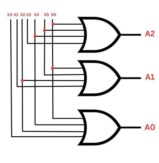
A diagram of the 8 to 3 key encoder circuit is drawn from simplified expressions indicated by the logic gates, as shown in the image below.
Circuit diagram of 8 to 3 priority encoder
8 to 3 models are available in the standard IC 74LS148, containing eight logic 0 or active low inputs and three logic '1' or active high output bits. Various features of this type of encoder include:
Cascading of n bits can be done for priority encoding.
It encodes for inputs having the highest priority.
Conversion of code.
Conversion of decimal to BCD
It enables the output line with active low when every input line is active high.
This is also called a 4-bit priority, which contains 4 inputs and 2 output lines as the encoder contains 2n number of input lines and n number output lines. And, The third output is 'V', which is considered a valid indicator but is set to 1 if more than one input line is high or active (1).
If the valid bit is '0', every input is '0'. Here, the other two output lines are depicted as don't care conditions symbolized by 'X'.
Following is the truth table of a 4 to 2 priority encoder :
D3
D2
D1
D0
A
B
C
0
0
0
0
X
X
0
1
0
0
0
0
0
1
X
1
0
0
0
1
1
X
X
1
0
1
0
1
X
X
X
1
1
1
1
The truth table above shows the inputs D3, D2, D1, D0 and Outputs A, B and valid bit indicator 'V'. Here D3 is the input with the highest priority, and D0 is the input with the lowest priority.
If the input D3 having the highest priority irrespective of every input line is active high (1), then the output in the 4-bit priority encoder is 11.
If the D3 input is active low and D2(the next highest priority irrespective of every input line) is active high, the output is BA = 10.
If the input D3 and D2 is active low, and D1(which has the next highest priority irrespective of the remaining input line) is active high, the output will be BA = 01
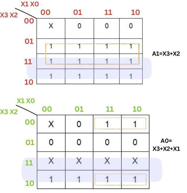
Output expression can be told in a 4-bit encoder with the help of a karnaugh map (K-map), as shown below.
Output expressions A and B were obtained using K-map
From the K-map shown above, simplified expressions for the outputs A and B results are obtained. The circuit diagram of the 4 to 2 priority encoder from these output expressions is displayed through logic gates below.
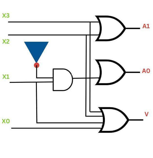
Circuit diagram of 4 to 2 priority encoder
The circuit diagram of the 4 to 2 priority encoder is obtained with two OR gates, and the combination of NOT gate and the AND gate stands for a valid bit, which is used when greater than one input is logic high (1). Therefore, 4 inputs with 2 outputs are encoded based on allocated priority.
Digital Encoder using Logic Gates
A combinational logic circuit known as a digital encoder changes one binary code input into another. Logic gates like AND, OR, and NOT gates are frequently used in their design. An 8-to-3 line encoder, for instance, converts eight input lines into three output lines. An AND gate has one input connected to each input line, and select lines are connected to the other inputs.
Next, OR gates are connected to the AND gates' outputs. The corresponding output of the OR gates creates the encoded output, while the select lines determine which input is active. This encoding procedure is helpful for applications like data transfer and address because it minimizes the number of output lines required to represent the input data.
Application of Priority Encoder
Following are the applications of priority encoder:
It reduces the number of wires and connections needed for electronic circuit designing with multiple input lines, keypads, and keyboards.
It is used to control the position in the ship's navigation and the location of the robot arm.
It is used to acquire the highest priority inputs in various microprocessor interrupt control systems' applications.
It protects the entire network from hackers by transmitting binary code to the network.
It is used to adjust the speed of industrial motors.
It is used in robotic vehicles.
Frequently Asked Questions
What do you mean by priority encoder?
It is a combinational logic circuit that comprises 2n input lines and n output lines and depicts the high priority input between all the input lines. When multiple input lines are simultaneously active, the highest priority input is considered first to produce output.
What is the difference between priority encoder and decoder?
A digital device known as a priority encoder gives input lines a priority and converts the highest-priority active input into binary code. By contrast, a decoder is a circuit that, depending on the input code, transforms binary input into a certain number of output lines.
How is a priority encoder different from a normal encoder?
A priority encoder assigns priority to inputs and encodes the highest-priority active input, whereas a normal encoder simply encodes the first active input without considering priority. In case of simultaneous activations, a priority encoder ensures the highest input is encoded.
What are the advantages of using a priority encoder?
Priority encoders eliminate the need for additional logic to handle simultaneous active inputs, ensuring the highest-priority input is always encoded. They simplify circuit design, reduce hardware complexity, and are efficient in applications like interrupt handling and data transmission.
Conclusion
A priority encoder plays a crucial role in digital electronics by efficiently encoding inputs based on priority, ensuring the highest-priority active input is selected. This eliminates ambiguity in situations where multiple signals are active simultaneously, making it ideal for applications like interrupt handling, multiplexing, and data compression.
We hope that this blog has helped you enhance your knowledge regarding priority encoders.


 8+ registered

